12
Transponder interfacing using relay:
If the vehicle has a transponder system installed, you will need to by-pass the system
while the vehicle is operating under the control of the Remote Start Unit.
To do this:
1.You will need a transponder key that's already programmed to the vehicle.
2.Remove the trim around the ignition switch.
3.Wrap a thin (28 - 30awg) wire tightly around ignition switch 6 to 8 times and secure it.
4.About 6"down line make another loop of approximately 2"diameter.
5.Place the key inside this loop and secure it to the loop.
6. Connect on end of the (28 - 30awg) wire to pin (87) of the relay module.
7. Connect the other end of the loop wire to Pin (30) of relay module.
8. Connect the pin (86) of the relay module to the ignition wire from the ignition switch.
9. Connect the pin (85) of the relay module to the H6/13 yellow wire of 20-pin connector.
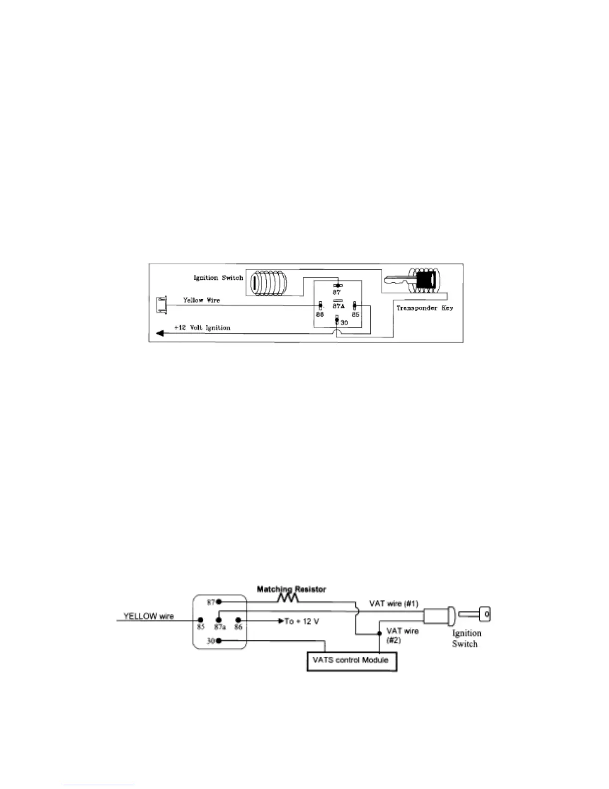
GM VATS KEY OVERRIDE:
If the vehicle has the General Motor VATS system installed, you will need to by-pass the
system while the vehicle is operating under the control of the Remote Start Unit. To do
this:
1. Measure the resistance of the resistor pellet on the ignition key then select a resistor
within 5% of the key's value.
2. Locate the pair of VATS wires in the vehicle, usually a pair of thin gauge wires running
from the ignition switch to the VATS control module
3. Connect the YELLOW wire from Remote Start Unit to TERMINAL #86 of an external
relay. Connect terminal #86 of the relay to a fused +} 2 volt
4. Cut (#1) wire (as shown), and connect the ignition switch side of the cut wire to terminal
#87a of the relay. Connect the other
side of the (#1) wire to terminal #30
5. Connect the previously seleted resistor from terminal #87 to the second(#2) wire (as
shown)
H6/14 GREEN WIRE—Negative Door Switch Sensing Input (Zone 3)—
This wire is the ground trigger input wire for negative door pin switch. This wire is
 Loading...