14
light circuit switches ground to the brake lights. An isolation diode must be used for ground
switched brake light circuits and must be connected to the output of the brake switch.
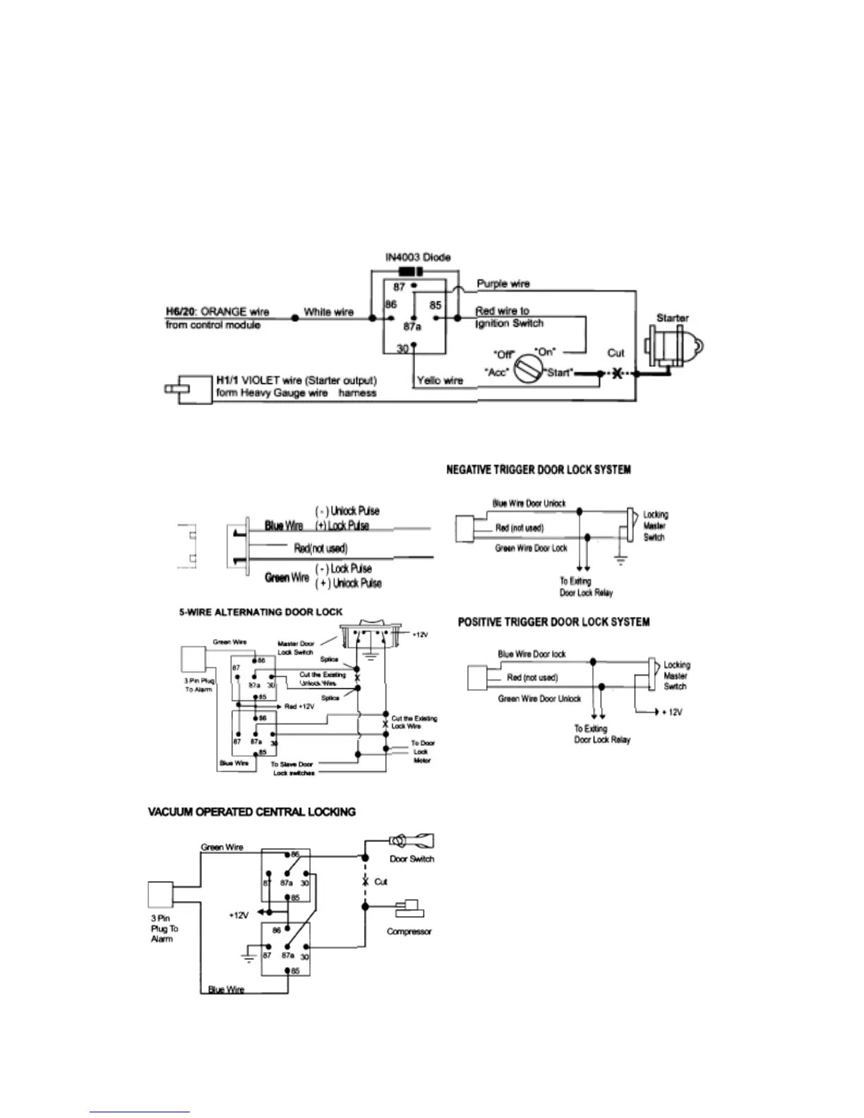
H6/20 ORANGE WIRE—(-)200mA Grounded Output When Armed-
This wire will become grounded when the alarm is armed. The current capacity of this
wire is 200mA. This output can control starter disable, when an intrusion is detected
and the system is triggered. The vehicles prevent from any unauthorized starting.
H4. 3 PIN DOOR LOCK CONNECTOR: (Maximum 500mA Output)
VACUUM OPERATED DOOR
LOCKING SYSTEM:
TYPICAL OF MERCEDES BENZ
AND AUDI.
Locate the wire under the drivers kick panel
Use the voltmeter connecting to ground, verify
that you have the correct wire with the doors
unlocked, the voltmeter will receive "12 volts'
Lock the doors and the voltmeter will read
"0 volt". Move the alligator clip to +12V and
the voltmeter will receive "12 volts'. Cut this
wire and make connections. Be sure to program
door lock timer to 3.5 seconds.
(See Alarm Feature B—3 Programming)
 Loading...