13
connection for "grounding" type factory door pins locate the "common wire' that
connects the door pin switches. Make the connection of the GREEN Wire here.
H6/15 GRAY WIRE—(-)200mA Channel 3 Output—
This will become a 1 second pulse ground by activate (button 3)
on transmitter for
two seconds, the current capacity of this wire is 200 mA. This feature allows you to
remote control trunk release or other electric device. (Realay may be required).
H6/16 BLUE WIRE—Ground Instant Trigger Input (Zone 2)—
This wire is the ground trigger input wire for hood and or trunk pin switches
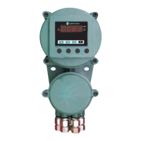
H6/17 WHITE/VIOLET WIRE—Positive Safety Shut Down Input—
This wire provides an instant shutdown for the remote start,
whenever it gets +12volts. If the brake lights switch in the
vehicle switches +12 volts to the brake light circuit, connect this
wire to the output side of the brake switch. This will allow the
remote start to shut down if an attempt is made to operate the
vehicle without the key while running under the control of the
remote start. In most vehicles, in order to gear, the brake
pedal must be depressed. The brake input will in turn cause the
remote start unit to shut off. See diagram.
H6/18 VIOLET WIRE—Positive Door Switch Sensing Input (Zone 3)—
This wire is the positive trigger input wire for positive door pin switch. This wire is
connection for "positive" type factory door pins(typical FORD MOTOR). Locate the
"common wire" for all door pins and make the connection of the VIOLET Wire here.
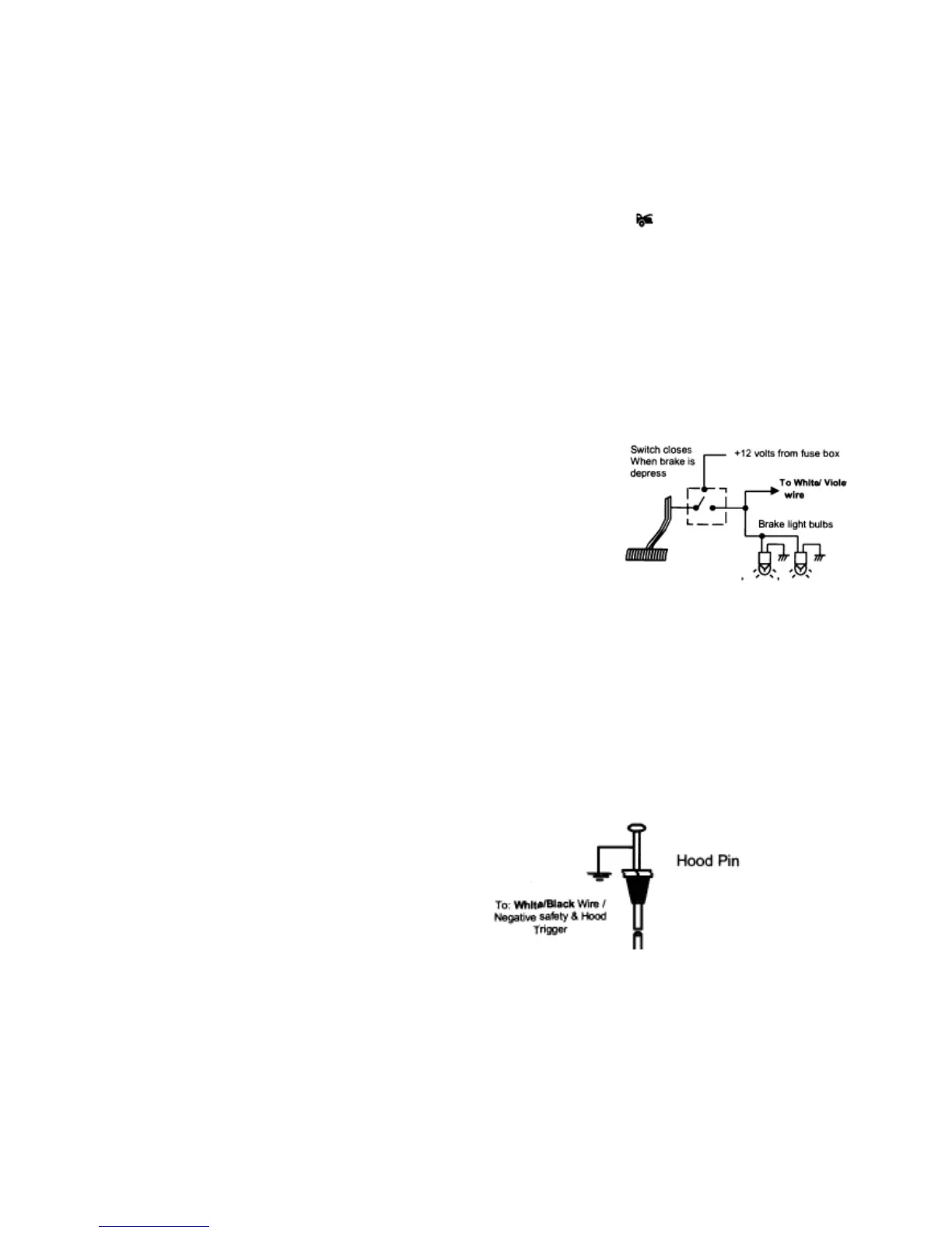
H6/19 WHITE/BLACK WIRE—Negative Safety Shut Down Input—Hood trigger Input
The WHITE/BLACK wire provides an
instant shutdown for the remote start,
whenever it is grounded. Connect the
wire to the hood pin switch previously
installed. This wire must be routed
though a grommet in the firewall and
connected to the hood pin switch. This
will also act as a hood trigger for the
alarm system
Important! This connection is a safety wire and must be connected as shown and
tested as specified. Failure to do so may result in personal injury or property damage. See
detail of wiring in the following diagram. This wire may also be used if the vehicle brake
 Loading...