2
UNI-335 manual
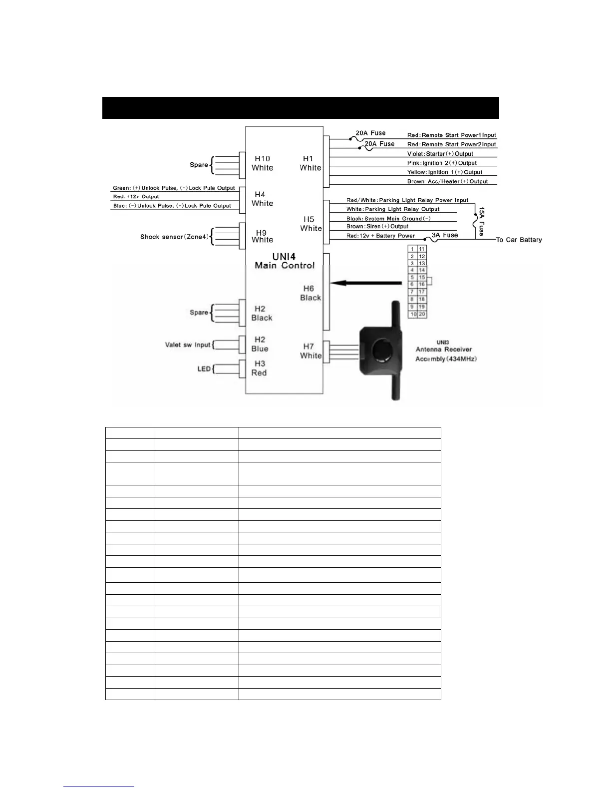
Pin Color Function
1 Brown/Black Ground Output While Running(Engine Run output)
2 Gray/Black Second Starter Output
3 Pink 2-Step Unlock/Factory Disarm/Sensor
By-pass
4 White/Blue Instant Start And Turn Off /Input
5 White Dome Light Control Output
6 Brown/White Horn Output (Programmable)
7 Black/Green Channel 4 Programmable Output
8 Black/White Neutral Safety Switch Input
9 Orange/White Ground Output When Disarmed
10 White/Red Tachometer Signal Input(RPM input)
Pin Color Function
11 Blue/Black Accessory 2 Control Output
12 White/Green Diesel Wait To Start Input
13 Yellow Ignition 3 Control Output
14 Green Zone 3(-)Negative Door Pin Trigger
15 Gray Channel 3(Trunk) Output
16 Blue Zone 2 Negative Hood/Trunk Trigger
17 White/Violet (+) Brake Switch Shutdown Input
18 Violet Zone 3 (+) Positive Door Pin Trigger
19 White/Black (-)Negative Hood Pin Safely Shutdown
20 Orange Ground Output When Armed
INSTALLATION DIAGRAM
 Loading...