VECTOR3MANUAL
MAN‐004REV7.2127/20/2017
2.Threadtheendofthesteeringlinethrough
theguideringlocatedontheriserthenthrough
thegrommetlocatedontoggle.
3.Loopovertheendofthetoggleasshown.
METHOD
C—SPECTRA(MICROLINES)LINES(WITHUNFINGERTRAPEDENDS)
Afterthemaincanopyhasbeenproperlyattachedtotherisersandwhileitisstilllyingonitsside,attachthetogglesto
itbyfollowingthesesteps:
1.Startingatthetailofthecanopy,tracetheuppersteeringlinesdownto
thelowersteeringline.Theideaistobe
surethesteeringlinesareroutedcorrectly;theyshouldnotwraparoundanysuspensionlines.Theright‐handsteering
linemustpassthroughtheright‐handrearslidergrommet,andtheleft‐handlinemustpassthroughtheleft‐handrear
slidergrommet.
2.Locatethemarkonthesteeringlinethatindicatesthecorrecttogglelocation.Verifythatthismarkisinthecorrect
locationbyreferringtothemaincanopyowner’smanual.
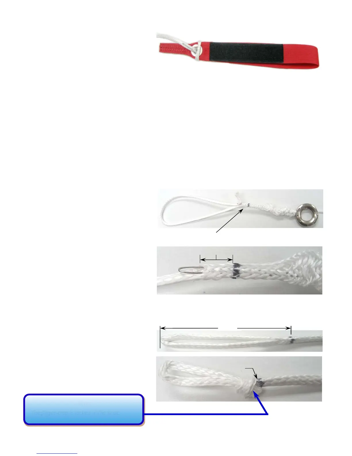
3.Usinganappropriatefingertrappingtool,
Beginthefinger‐trapasshowtotheright.
4.Thefinger‐trapmustbeginfrom3/8”to1/2"
frommarkasshown.Thiswillensurethatthe
finger‐trapislockedintheknot.
5.Formafinger‐trappedloop2”fromthe
manufacturersmarktotheendasshown.
6.Tieandadjustan
overhandknotuntilthe
markisjusttotheoutside.Theloopshouldfit
closelyaroundthetoggle.Tightentheknot.
3/8”to1/2"
2”
Mark
3.
3.
4.
5.
6.
NOTE
Thefinger‐trapislockedintheknot.