2.5. Tool I/O
Parameter Min Typ Max Unit
Input voltage in voltage mode -0.5 - 26 V
Input voltage in current mode -0.5 - 5.0 V
Input current in current mode -2.5 - 25 mA
Input resistance @ range 0V to 5V - 29 - kΩ
Input resistance @ range 0V to 10V - 15 - kΩ
Input resistance @ range 4mA to 20mA - 200 - Ω
An important thing to realize is that any current change in the common GND
connection can result in a disturbing signal in the analog inputs, because there
will be a voltage drop along the GND wires and inside connectors.
Note that a connection between the tool power supply and the analog inputs
will permanently damage the I/O functionality, if the analog inputs are set in
current mode.
To make it clear how easy it is to use digital inputs, some simple examples are
shown.
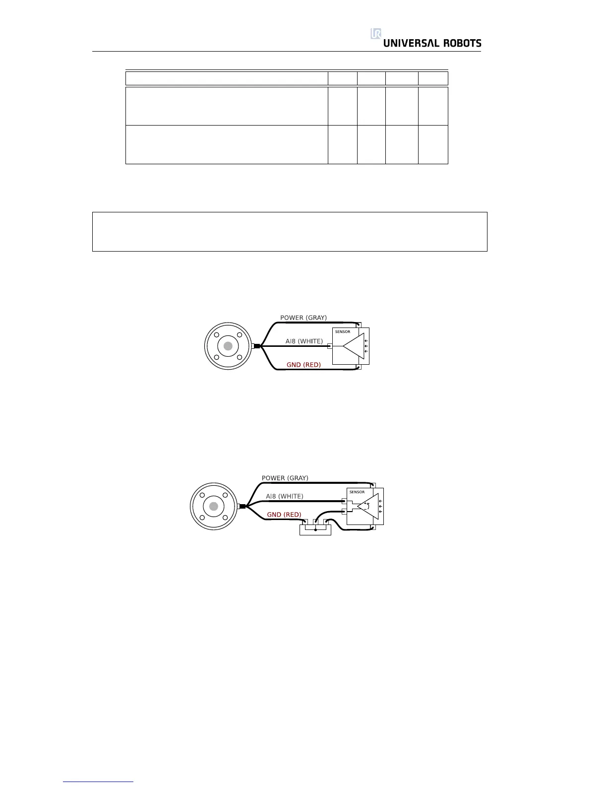
Using Analog Inputs, Non-differential
The simplest way to use analog inputs. The output of the sensor can be either
current or voltage, as long as the input mode of that analog input is set to the
same on the I/O tab. Remember to check that a sensor with voltage output can
drive the internal resistance of the tool, or the measurement might be invalid.
Using Analog Inputs, Differential
Using sensors with differential outputs is also straightforward. Simply connect
the negative output part to GND (0V) with a terminal strip and it will work in the
same way as a non-differential sensor.
All Rights Reserved
29 UR10
 Loading...


