A.2. Robot and IMM integration
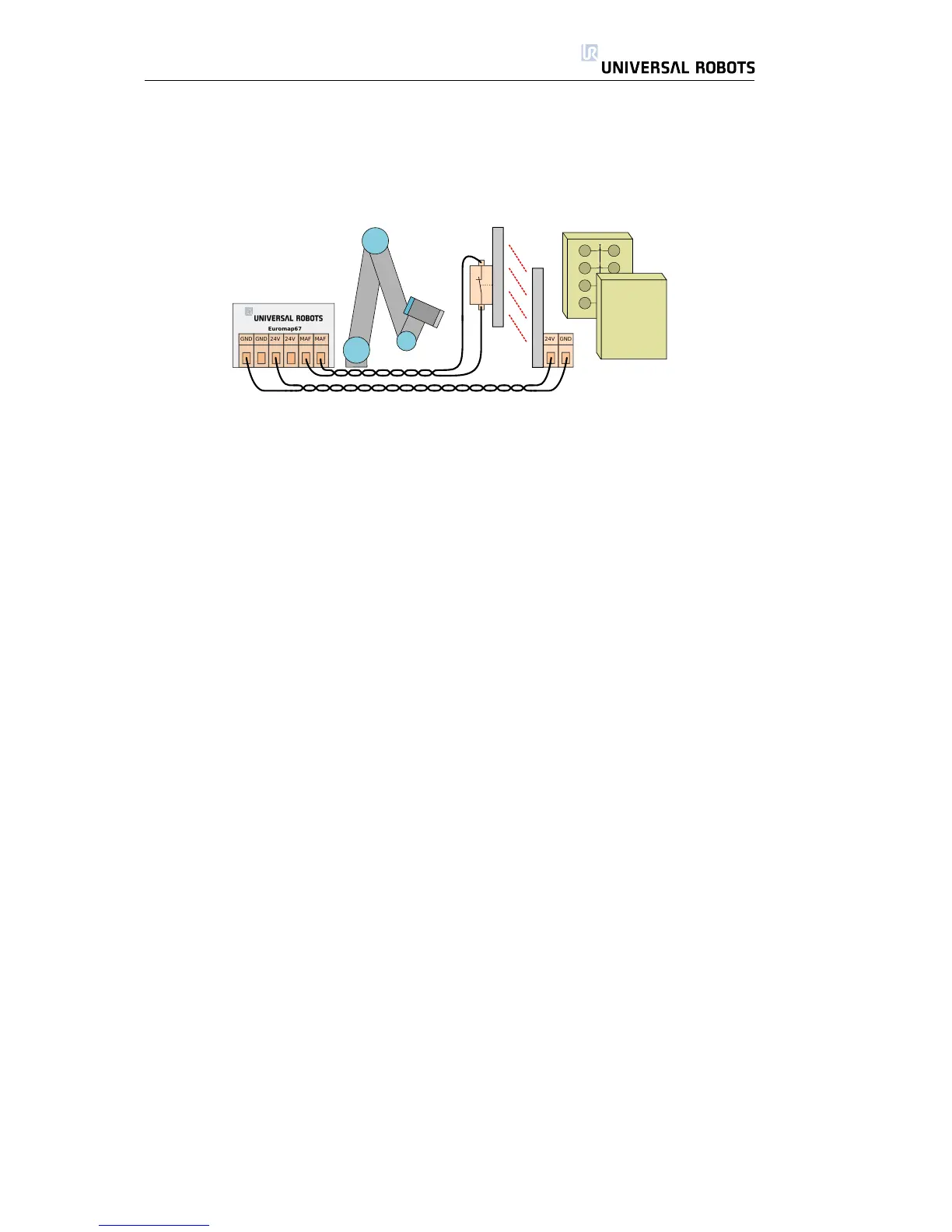
The euromap67 interface is supplied without a MAF light guard. This means
that an error in the robot program could cause the IMM mould to close and
crush the robot. However, it is possible to connect a light guard as shown below
to prevent these accidents. A category 1 light curtain can be purchased for a
few hundred Euro (e.g. ”PSEN op 2H-s/1” from Pilz).
A.2.3 Mounting the robot and tool
Before constructing a tool and a mounting surface, the integrator must consider
how joint 4 (wrist 2) is orientated during pick and place. Joint 1, 2 and 3 has
parallel axes and if joint 4 orientates joint 5 to the left or to the right then joint 5 is
parallel to the other three axes, which forms a singularity. It is generally a good
idea to place the robot in a 45 degree angle or constructing a tool where the
surface of the tool flange of the robot points down when gripping the items from
the vertical mould surface.
A.2.4 Using the robot without an IMM
To operate the robot without an IMM, a by-pass plug must be used to close the
emergency and safety signals. The only alternative is to permanently uninstall
the interface as described in section A.4.1.
A.2.5 Euromap12 to euromap67 conversion
To interface an IMM with euromap12 interface an E12 - E67 adaptor must be
used. Several adaptors is available on the marked from different manufactur-
ers.. Unfortunately most adaptors are constructed for specific robots or IMMs
assuming specific designs choices. This means that some adaptors will not con-
nect the UR robot and your IMM correctly. It is recommended to read both
the euromap12 and euromap67 standard whenever using or constructing an
adaptor.
A list with common errors is shown below:
1. Do you measure 24V between A9 and C9?
• The IMM must supply 24V to enable the I/O signals.
• If the robot and the IMM has common minus/0V then the robot 24V
can be used by connecting A9 to ZA9 and C9 to ZC9. IMM 24V is often
present at euromap12 pin 32.
2. Is the adaptor switching both robot emergency channels and both robot
safety devices channels?
• This is typically accomplished using 4 relays.
All Rights Reserved
45 UR10