A.3. GUI
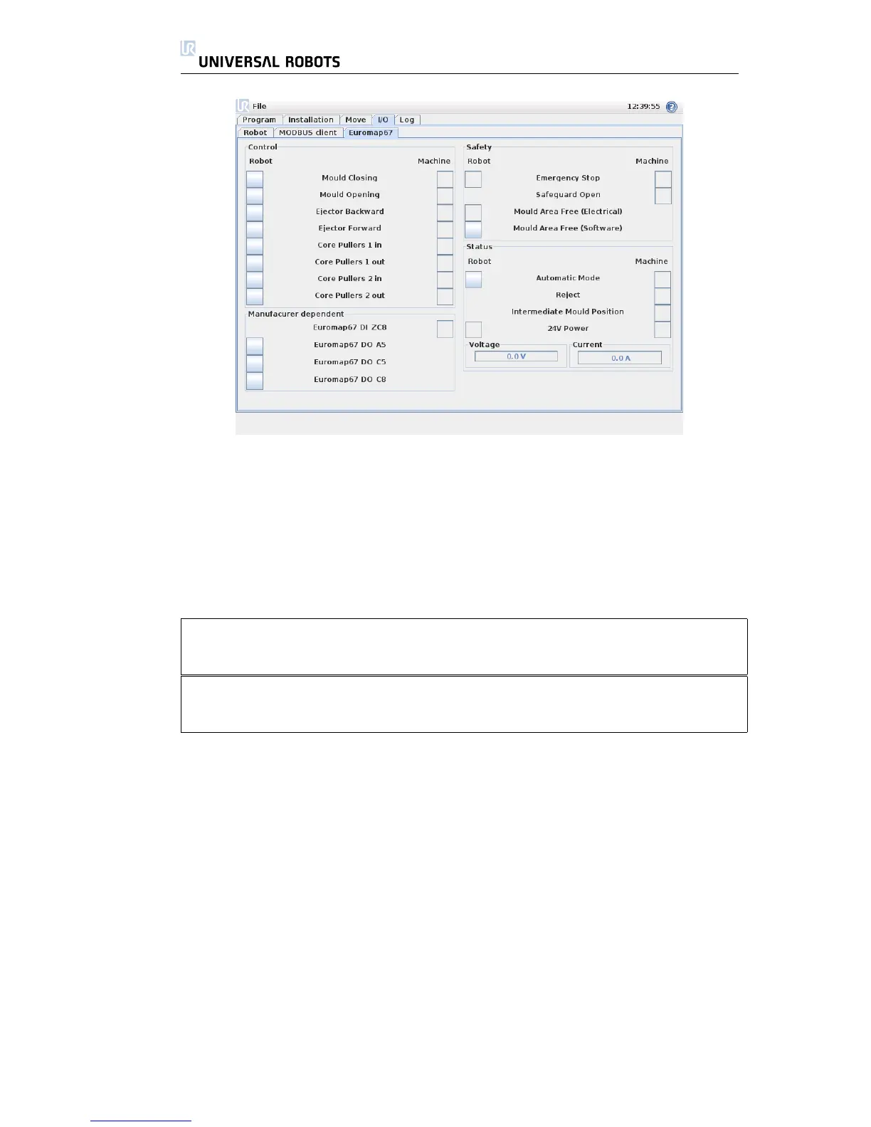
There are four frames on this screen, which are described separately below.
Common for all are the two columns Robot and Machine, which respectively
shows buttons for controlling output signals, and indicators for showing state of
input signals.
The (normal) state of the signals at startup, is that they are all low, except for
the 24V signals, and the robot output Automatic Mode which is active-low and
therefore set high per default.
If a signal is not part of a program structure, and it is intended to be used in
a robot program, this is achievable making use of e.g. Action and Wait nodes.
NOTE: ”Automatic mode” from the robot to the IMM is active low. The button
reflects the physical level and therefore ”Automatic mode” is activated when
the button is not activated.
NOTE: The buttons for controlling output signals are per default only availabe in
robot programming mode. This can, however, be set as desired on the I/O setup
tab found on the Installation screen.
Control
The signals related to controlling the interaction between the robot and the IMM
are shown here. These signals are all used by the program structures, where they
have been joined in appropriate and secure ways.
Manufacturer dependent
These are signals, that may have specific purposes according to the IMM manu-
facturer. The robot is not dependant on specifics of these signals, and they can
be used as needed.
Safety
In the robot column, the indicators Emergency Stop and Mould Area Free (Elec-
trical) are not controlable from this screen. They simply indicate if the robot is
emergency stopped, and if the MAF output is set high. The MAF output is set
All Rights Reserved
48 UR10
 Loading...


