6 | uponorpro.com
24
VAC
24
VAC
24
VAC
24
VAC
24
VAC
24
VAC
24
VAC
24
VAC
24
VAC
24
VAC
24
VAC
24
VAC
03
01 08 1203
02a 02b01b01a 09 10 11 12080704 05
030201 04 05
06
A3800165 A3800165A3800167
3801165 A3801160
Option
A or B
Option
A or B
Option A Option B
T
S
T TT T
06
T
Note: Refer to page 37 for additional
wiring information.
Caution: Only 24 VAC
Uponor actuators are
compatible with the
base unit.
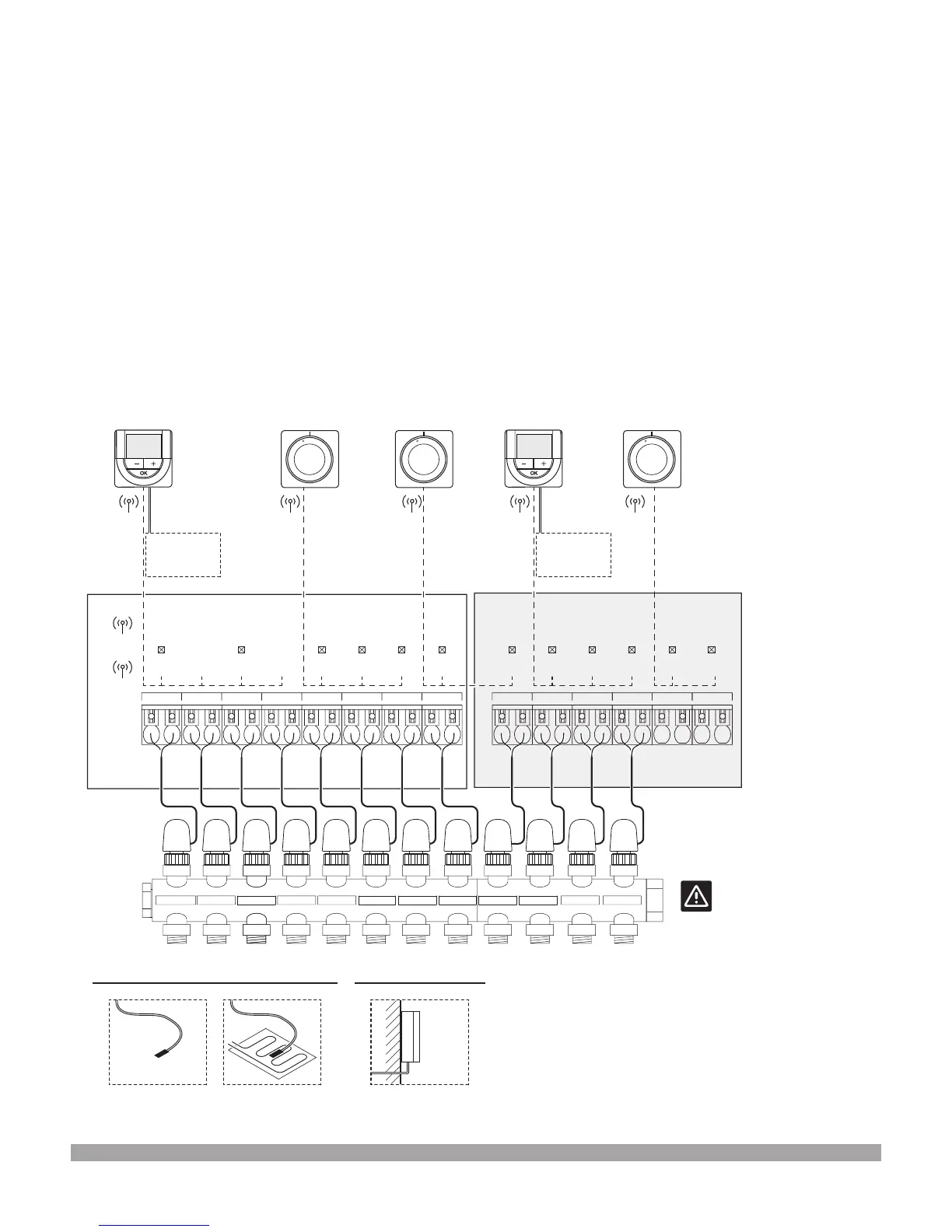
Installation example
The gure below shows an installation example of the
base unit (six channels) with an optional expansion module
(six extra channels) using thermostats and actuators.
Thermostats will regulate each room according to their set
temperatures.
• Thermostat 01 controls the actuators on channels
01a, 01b, 02a and 02b with an optional AC sensor.
• Thermostat 03 controls the actuators on channels 03 to 05.
• Thermostat 06 controls the actuators on channels 06 and 07.
• Thermostat 08 controls the actuators on channels 08 to 10
with an optional AC sensor.
• Thermostat 12 controls the actuators on channels 11 and 12.
Option A
• External temperature sensor
• Floor temperature sensor
Option B
• Outdoor temperature sensor
Figure 2-2: Installation example
 Loading...