10 | uponorpro.com
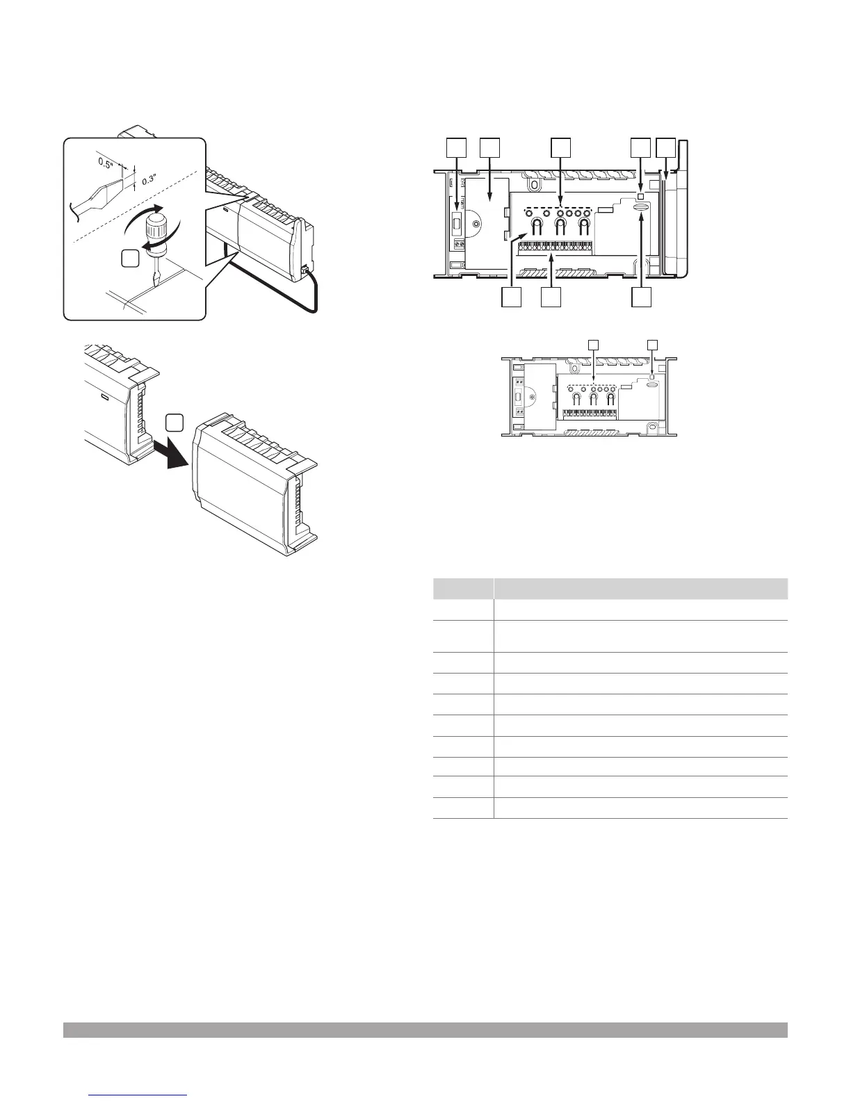
Removing the expansion module
The illustration below shows how to remove the expansion
module from the base unit.
1
1.2 mm
8 mm
2
1. Place a wide, at-head screwdriver in the slot between
the expansion module and the other unit and twist until
the snap-in lock releases. Repeat for the other side.
2. Remove the expansion module. Use caution not to bend
the connection pins.
Connecting components to the base unit
Refer to the wiring diagram found at the end of this document.
The illustration below shows the inside of the base unit.
Item Description
A Fuse
B Optional inputs and outputs for pump management,
boiler managment
C Channel registration buttons
D LEDs for channels 01 to 06
E Quick connectors for actuators
F MicroSD card
G Power LED
H Wireless antenna
I LEDs for channels 07 to 12
J Wireless Base Unit Expansion Module (A3801160)
Figure 3-10: Removing the expansion module
Figure 3-11: Connecting components to the base unit

 Loading...