Climate Control Zoning System II installation and operation manual | Chapter 7 – Operating digital thermostats l 25
Chapter 7
Operating digital thermostats
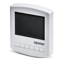
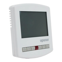
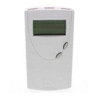
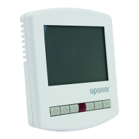
Thermostat components
The illustration below shows the parts of the thermostat.
Item Description
A Display
B Buttons
C Terminal for external sensor (non-polarised)
D Batteries
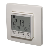
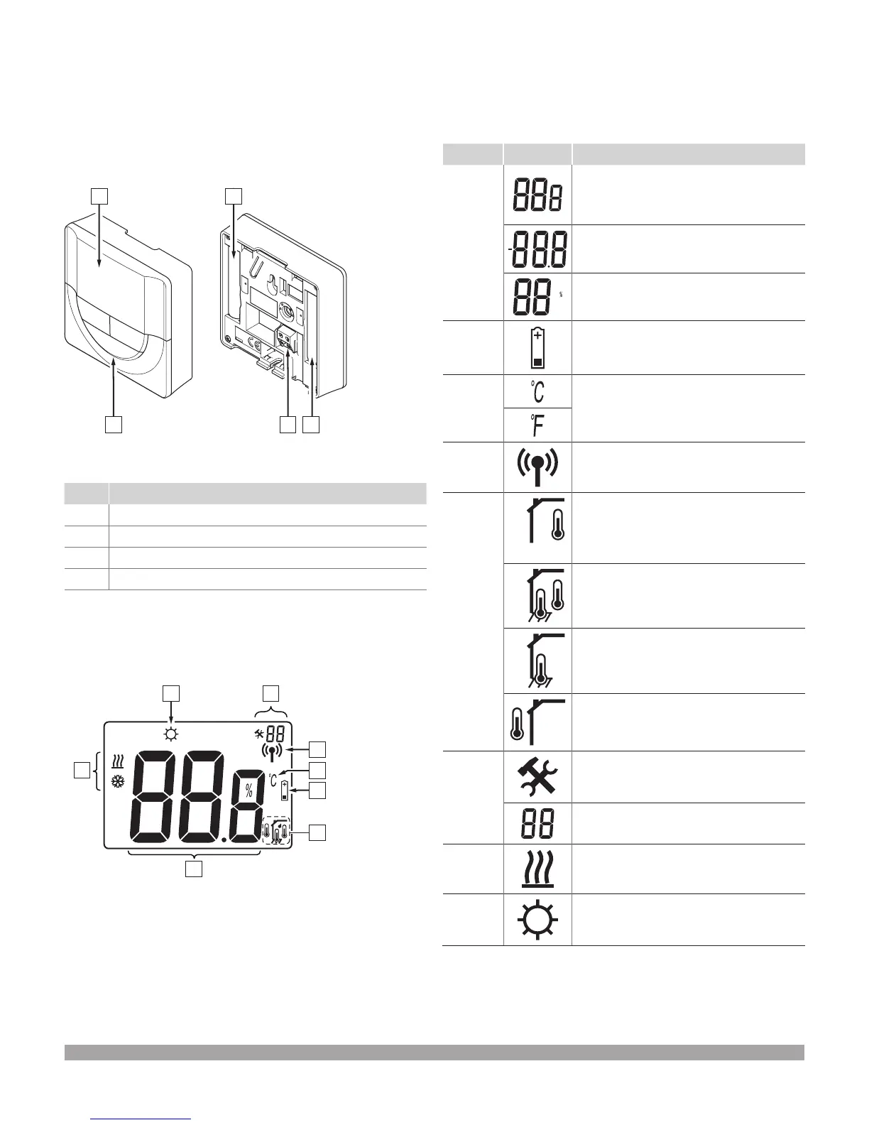
Display layout
The gure below shows all possible symbols and characters that
can be shown on the display.
D
C
B
E
G
Item Icon Description
A
Message field using three
alphanumerical characters
Temperature reading using a – or + sign,
two digital characters, a decimal point
and a character showing either 0 or 5
Relative humidity reading using two digital
characters, indicated with a “%” character
B
Low battery indicator
C
Temperature unit, shown when the character
group A shows a temperature
D
Communication indicator
E
Indoor temperature indicator
Remote sensor temperature indicator
(RS mode)
The text Err and a flashing sensor icon
indicates a faulty sensor.
Indoor temperature with floor temperature
limitation indicator
The text Err and a flashing floor sensor icon
indicates a faulty sensor.
Floor temperature indicator
The text Err and a flashing floor sensor icon
indicates a faulty sensor.
Outdoor temperature indicator
The text Err and a flashing outdoor sensor
icon indicates a faulty sensor.
F
Settings menu
Settings menu number
G
Heating demand
H
Comfort mode
Figure 7-1: Digital thermostat components
Figure 7-2: Display layout

 Loading...