Climate Control Zoning System II installation and operation manual | Chapter 4 – Installing thermostats and sensors l 15
Chapter 4
Installing thermostats and sensors
The following thermostats can be connected to the system:
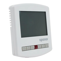
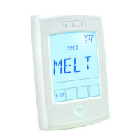
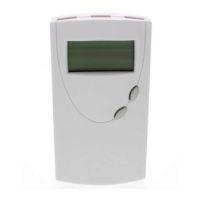
• Wireless Dial Thermostat (A3800165)
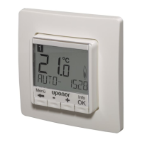
• Wireless Digital Thermostat (A3800167)
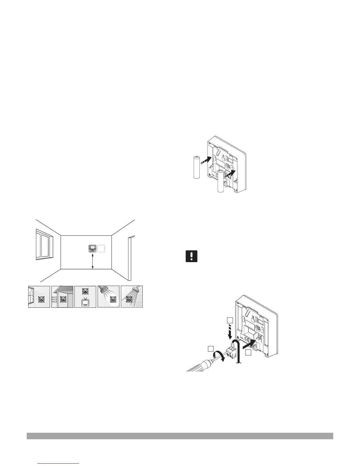
Thermostat placement
Refer to the following guidelines when positioning
the thermostats:
1. Select an indoor wall and a distance 5 ft. (1.5 m)
above the oor.
2. Ensure the thermostat is away from direct solar radiation.
3. Ensure the thermostat will not be heated through the wall by
sunshine.
4. Ensure the thermostat is away from any source of heat
(e.g. television set, electronic equipment, replace, spotlights).
5. Ensure the thermostat is away from any source of humidity
and water contact.
6. Ensure the thermostat is positioned at least 1.3 ft. (40 cm)
away from the controller to avoid interference.
5 ft./1.5 m
Labeling thermostats
Label the thermostats, where suitable, with the channel
numbers they are to control (e.g. 02, 03). For a system
with several controllers, add the ID of each controller
(e.g. 1.02, 1.03, 2.02, 2.03).
If the thermostat can connect to an external sensor,
add information about sensor type when applicable.
Available thermostat and sensor combinations:
• Room temperature
• Room and oor temperature
• Room and outdoor temperature
• Remote sensor temperature
Inserting batteries
All thermostats use two alkaline 1.5 V AAA batteries which
provides about two years of battery life, as long as they are
positioned within radio range of the base unit. Ensure the
batteries are correctly inserted into the thermostats.
After inserting the batteries, the thermostat will perform a
self test for about 10 seconds. The system will block for input
and the thermostat LED ashes during this period.
The illustration below shows where to insert the batteries.
Connecting an external sensor
to a thermostat (optional)
An optional external sensor can be connected to the digital
thermostats (A3800167) for extra functionality.
Important! For accurate temperature, attach the
outdoor sensor to the north side of the building
where it is unlikely to be exposed to direct sunlight.
Do not place it close to doors, windows or air outlets.
Connect the sensor to the terminal located at the back of
the thermostat, as shown in the illustration below.
3
1
2
1. Insert the two wires from the sensor cable (non polarized)
into the removable connector.
2. Tighten the screws, xing the wires in the connector.
3. Insert the connector on the input pegs on the thermostat.
Figure 4-1: Thermostat placement
Figure 4-2: Inserting batteries
Figure 4-3: Connecting an external sensor

 Loading...