Climate Control Zoning System II installation and operation manual | Chapter 8 – Maintenance l 29
Chapter 8
Maintenance
Manual preventive maintenance
The system requires no preventive maintenance except
cleaning with a dry, soft cloth.
Warning! Do not use any detergents to clean
the Climate Control Zoning System II.
Automatic preventive maintenance
The system is equipped with an automatic exercise function
that consists of a test run designed to prevent the pump and
actuators from seizing up due to inactivity.
This exercise is run every six days ±24 hours at random.
• The pump exercise operates only if the pump has not been
activated since the last exercise. The pump is activated for
3 minutes during the exercise.
• The actuator exercise operates only if the actuators have not
been activated since the last exercise. The exercise consists
of opening and completely closing the actuators periodically.
Corrective maintenance
Fallback mode
If a thermostat is malfunctioning or not detected, the controller
executes the fallback mode to maintain the temperature in the
room until the problem is resolved.
Resetting the controller
If the controller does not work as expected, for example
due to a hang-up, it can be reset to solve the problem.
1. Disconnect and reconnect the controller to AC power.
Controller LEDs
Uponor recommends occasionally checking the power
LED on the controller for alarms. The power LED ashes
continuously for general alarms. Determine which thermostats
are issuing alarms by removing the cover. If a channel
LED is indicating an error, check the function and batteries
of the registered thermostat.
The controller power LED is on during normal operation.
All the channel LEDs are off when there is no current or
waiting actuator activity. The LEDs turn on when the
corresponding actuators are activated or start ashing
when they are awaiting activation.
Up to eight actuators in six rooms can be in the opening process
at the same time. If a slave module is installed, the LEDs of the
seventh and subsequent actuators ash while they are waiting
for the previous actuators to be fully open.
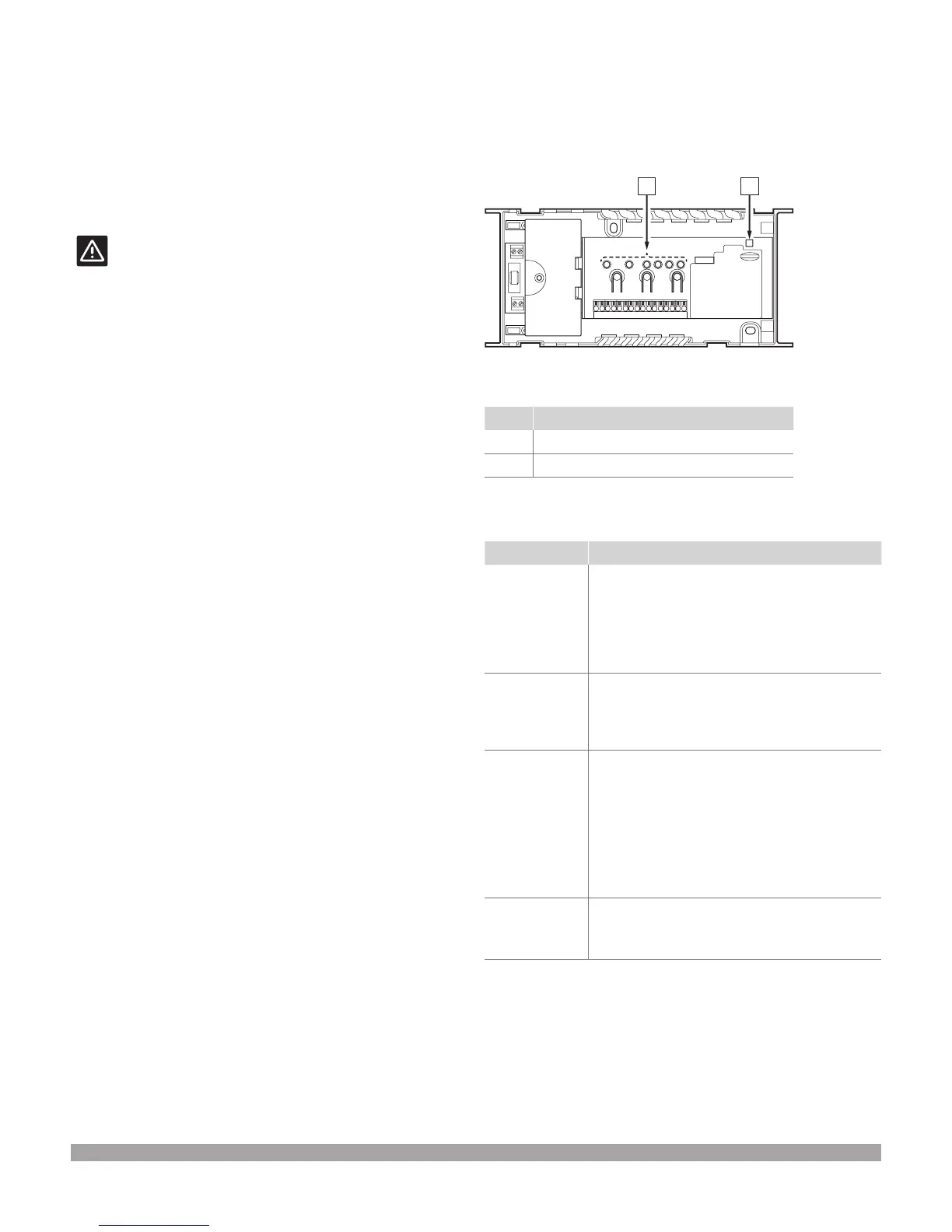
The illustration below shows the position of the controller LEDs.
Item Description
A Power LED
B Channel LEDs
The table below describes the status of the base unit LEDs.
LED Status
Power The base unit power LED is always on and ashes
when a problem occurs, such as:
• Loss of radio transmission from a thermostat
for more than 1 hour
• Loss of radio transmission from a timer or an
interface for more than 15 minutes
Channel during
run mode
• Red, on – actuators activated
• Red, ashing – thermostat communication
error or low battery indication
• Off – no demand for heating or cooling
Channel during
registering
mode
• Red, on – thermostat registered but with
communication errors
• Green, on – thermostat registered and
communication is OK
• Red, ashing – selector pointing at channel
• Green, ashing – channel selected to
be registered
• Off – channel not pointed, nor registered
Channel during
forced mode
• Red, on – actuators activated
• Red, ashing – selector pointing at channel
• Off – channel not pointed, nor activated
Figure 8-1: Controller LEDs
 Loading...