16 l Smatrix Pulse | Installation and Operation Manual
Installation Overview
• The example system has five (5) heating zones and one
(1) cooling zone (Main Floor).
• The Main Floor is registered to Channel 1 but has no
actuator(s). This is due to the system controlling forced-
air heating and cooling but no radiant. In instances like
this, the thermostat needs to be assigned to a channel
(in this case, 1) and registered to the relay.
• Bedrooms thermostat is assigned to Channels 2 and 3
and will control actuators connected to 2A, 2B, and 3.
• Family Room heating will open actuators connected to 4
through 6.
• Master Bath heating will open actuators connected to 7.
• Garage thermostat is assigned to Channel 8, but no
actuator is connected. The Garage thermostat is also
linked to a relay module to operate a zone pump on a
call for heating.
Caution!
All thermostats need to be registered to a
controller for it to appear in the app
Hardware Handling
• The Primary Controller is the device that is connected to
the Communication Module. All others are sub-Controllers.
• A system does not require a Primary Controller, however,
system functionality will be limited.
• Sub-Controllers can only be registered to the Primary
Controller.
• Relay modules can be registered to both Primary and
sub-Controllers.
• The Digital Thermostat (T-169) (part number A3800169) is
the only thermostat that can connect to a Relay Module.
• A thermostat can only be linked to one Controller.
• The Controller will time out after 10 minutes of inactivity
and revert to normal operation. The timer is reset when a
button has been pressed.
• If programmed schedules exist, individual rooms may
operate without following a schedule.
• Setting up a system for remote access and connectivity
will require a mobile device (e.g., smartphone, tablet,
etc.).
A380265C/A380265A Controllers
Controllers are designed for modular installation, meaning
the individual parts (Transformer, Controller, Expansion
Module, and end cap) easily snap together. However,
should the installation require it, the power supply, or
Transformer (part number A3850050), can be mounted
separately.
Caution!
The Transformer is heavy and might detach if the
Controller is held in a vertical position (or upside
down) without the cover on.
Caution!
The Expansion Module must be attached by
snapping it into place due to connection pins used
for connecting to the Controller.
Note
Wires between the Transformer and the Controller
must be disconnected prior to detaching the
Transformer.
The components can snap on or off without needing to
remove the covers or by sliding them into place when the
covers are removed.
Note
Only one Expansion Module is supported per
controller.
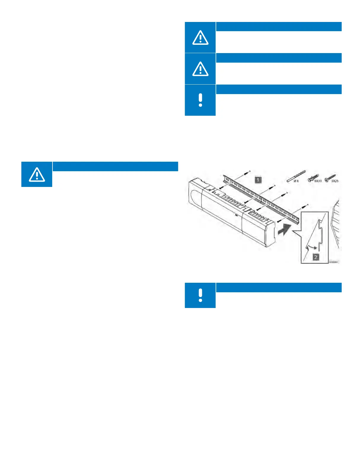
Mounting the Controller
• Find a suitable location in proximity to the manifold and
115V power supply/outlet.
• Remove the DIN rail from the package and place on the
wall and level. Note that the DIN rail included will support
both the Controller and the Transformer.
• Mark a minimum of two locations per DIN rail for screw or
anchor locations.
• Install the DIN rail onto the wall surface using the
necessary hardware.
• Assemble or connect all components prior to installing
on to the DIN rail.
• Snap the assembled hardware onto the DIN rail.
Figure 5-2: Mounting the Controller