uponor.com l 23
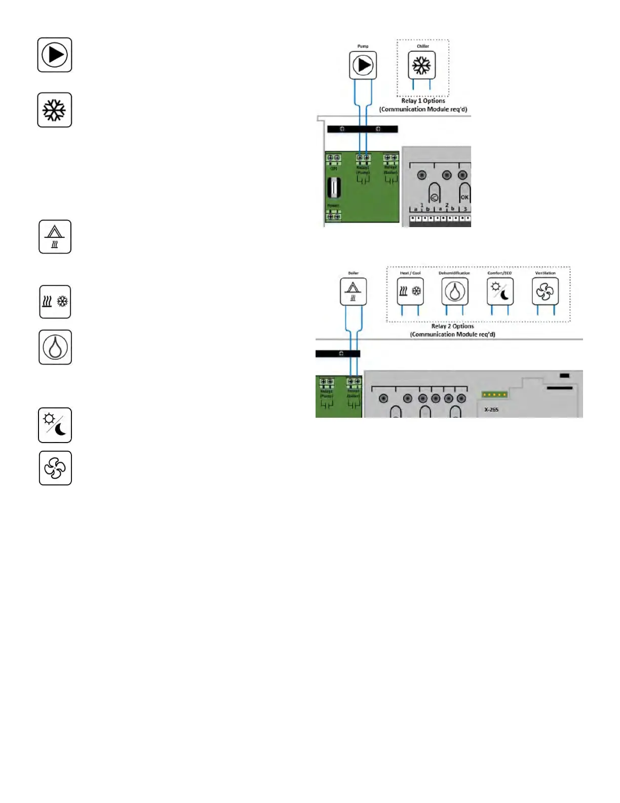
Pump: The output will close (turn on) when there
is a demand for heating or cooling. The relay will
open when the heating or cooling demand has
ended.
Chiller: The output will close (turn on) when the
system mode is set to cooling and there is a
cooling demand. The relay will open when the
cooling demand is met, or the mode is changed
to heating.
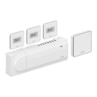
Relay 2 can be wired to a boiler (default) or other
options as shown in Figure 6-4 and will require
the Communication Module to change the default
functionality.
Boiler: The output will close (turn on) when there
is a heating demand. The relay will open when
the heating demand has ended. See Section
x for additional information on setting pump
operation to Individual or Common.
Heat/Cool: Heating is activated when the relay
is open; cooling is activated when the relay is
closed.
Dehumidification: The dehumidifier starts (relay
closed) when the relative humidity setpoint
is reached when in cooling mode. It will open
when the minimum run time of 30 minutes has
finalized and when the relative humidity has
decreased below the defined RH setpoint.
Comfort/ECO: The relay closes when ECO mode
is activated and open when the system returns
to Comfort mode.
Ventilation: The relay is closed when the
system is set to ECO. The ventilation unit must
be setup to lower its speed (see manufacturer’s
specifications) when the input is closed (ECO),
and to switch back when the input is opened
again (Comfort).
After all actuator and wiring connections are complete,
it is now time to power up the controller. Close the wiring
compartment and plug the controller into a 115V wall
outlet.
Relay Module (M-263)
The relay module adds two extra output relays to the
controller increasing the total amount of controller output
relays to four (4). This presents an option to control remote
components (within radio range) otherwise wired to the
Controller and/or up to four (4) components by the same
Controller.
If more than one Controller is available in the system, one
Relay Module per Controller can be used.
If conventional forced-air heating and cooling equipment
or fan coils are installed, a maximum of four (4) Relay
Modules can be used per Controller.
The function for the Relay Module is set in Installer Settings
during setup (requires a Communication Module). The
tables below show the available functionality depending
on the device it is linked to.
Figure 6-3: Relay 1 options
Figure 6-4: Relay 2 options