18 l Smatrix Pulse | Installation and Operation Manual
6.375" (162 mm)
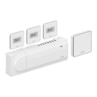
Figure 5-7: Relay
Module installation
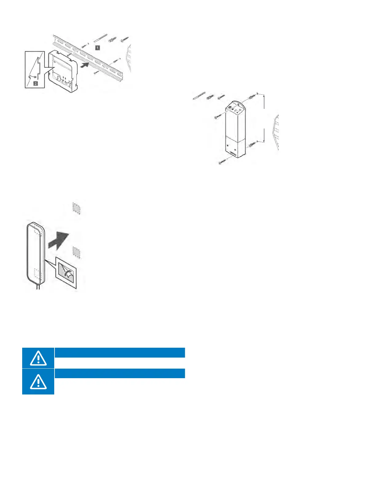
• Attach the
DIN rail to the
wall using the
appropriate
hardware.
• Snap the back
mount onto the
DIN rail.
Option 2: DIN Rail Back-Mount Case
Figure 5-5: Attaching case to DIN rail
Figure 5-6: Antenna
installation
• Route the Ethernet cable through the left opening on the
bottom of the case and connect to the Communication
Module
• There are two connections on the back of the
Communication Module. Connect to the port showing
the picture of the Controller.
• Install the Communication Module into the back mount.
• A click should be audible with a completed connection.
• Apply gentle pressure pulling down on the Ethernet cable
to ensure the connection is secure.
Antenna (A-265)
The Antenna is packaged with
a Controller in part number
A380265A. The Smatrix Pulse
system can be installed
with antennas only and no
Communication Module, so be
aware that system functionality
will be limited (see Chapter 4:
System Functionality). When
installing a system solely with
antennas, each Controller will
operate independently. When
installing and linking a Controller
in a system with a Controller that
is connected to a Communication
Module (primary), additional
Controllers with Antennas become
sub-Controllers.
Caution!
Install the Antenna outside a manifold cabinet.
Caution!
Install the Antenna vertically to ensure the best
communication.
Mounting the Antenna
• Attach the Antenna to the wall using the adhesive strips
included in the packaging.
Connecting the Antenna
• Route the Ethernet cable attached to the Antenna and
plug it into the connection on the bottom right hand of
the Controller.
• A click should be audible with a completed connection.
• Apply gentle pressure pulling down on the Ethernet cable
to ensure the connection is secure.
A3801263 Relay
Module (M-263)
Using a Relay Module
helps integrate other
systems (forced air/
fan coils, etc.), simplifies
or reduces wiring
complexity, and provides
a solution where it is
difficult to run wires to
activate heating (and
cooling) equipment.
Different functionality combinations are available when
using the Relay Module. To access these requires the
Communication Module.
Placing the Relay Module
Use the following recommendations when determining the
location of the Relay Module:
• Locate the Relay Module close to the device it will control.
• Place the Relay Module above the device(s) to avoid
potential water damage.
• Ensure the Relay Module is protected from exposure to
water.
• Check to make sure the cover can be easily removed
(there is proper clearance) and the terminals are easily
accessible.
Mounting the Relay Module
• Attach the Relay Module to the wall or surface.
• Use suitable hardware included in the packaging to
secure the Relay Module to the determined locations.