22 l Smatrix Pulse | Installation and Operation Manual
Output Relays
The Controller includes sets of output terminals that can
be operated independently to control external equipment,
such as a pump or boiler (default). Table 6-1 shows the
various options for these outputs if a Communication
Module is installed in the system. This table applies to
options for the Primary Controller (connected to the
Communication Module).
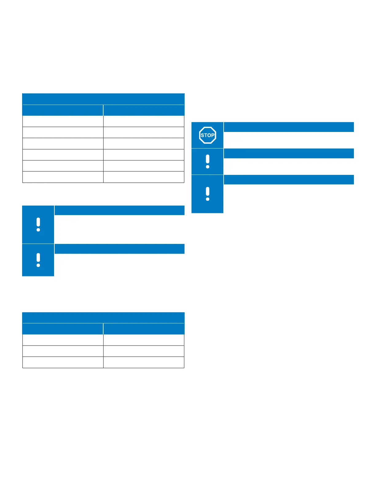
Primary Controller
Relay 1 Relay 2
Pump (default)
1
Boiler (default)
Pump
1
H/C Switch
3
Pump
1
Dehumidifier
5
Chiller
1,3
Boiler
Pump
1
Comfort/EC0
6
Not Configured Not Configured
Table 6-1: Relay Outputs
Note
A Relay Module can be used in installations where
the distance between the device(s) and the
Controller makes wiring difficult or if more outputs
are needed.
Note
All relays are dry contacts and require a power
source.
If a Controller is installed in the system as a sub-Controller
(connected to an Antenna), the options for assigning
functionality is different and limited.
Sub-Controller
Relay 1 Relay 2
Pump
2
H/C Switch
4
Pump
2
Dehumidifier
5
Not Configured Not Configured
Table 6-2: Relay Outputs
Relay Functionality Notes for Tables 6-1
and 6-2
1
H/C Switch and Chiller is only available when cooling is activated
2
Function only available when Pump management is set to Individual,
otherwise "Not used" is shown in the Smatrix Pulse App.
3
Function only available when cooling is activated.
4
Function only available when cooling is activated, otherwise "Not used" is
shown in the Smatrix Pulse App.
5
Function only available during relative humidity control (in cooling, no
fan coils).
6
This function is also used when connecting a ventilation unit.
Relays 1 and 2
Warning!
Risk of electrical shock! Disconnect or remove
power prior to making electrical connections.
Note
Additional relay will be required when wiring to a
pump or circulator. See wiring schematics.
Note
Chiller relay function requires a Communication
Module and must be set in Installer Settings during
initial configuration, or in the System Settings
Menu.
• Remove the cover from the Controller.
• Open the wiring compartment using a T-10 bit.
• Route the wires from the pump relay through the cable
entry above the contacts.
• Ensure the two actuator wires are stripped to
approximately
33
/88" (9.5 mm).
• Insert wires into terminal blocks and tighten with a small
screwdriver.
Relay 1 can be wired to a pump (default) or chiller as
shown in Figure 6-3 and will require the Communication
Module to change the default functionality.