4. Route the cables from/to the heat pump via a cable
entry.
5. Connect the signal cable receiving from the heat
pump to the connection labelled IN.
6. Connect the signal cable sending to the heat pump
to the connection labelled OUT.
7. Secure the cables to/from the heat pump with cable
clamps in the enclosure.
8. Close and secure the lid to the optional connections
compartment.
Connect dehumidifier (Wave PLUS with
interface only)
The system can control up to four dehumidifiers, one
per controller, connected through a relay module. The
dehumidifier starts when the relative humidity setpoint
is reached when in cooling mode. It will stop when the
minimum run time of 30 minutes has finalized and when
the relative humidity has decreased below the defined
RH setpoint - deadzone.
NOTE!
See the dehumidifier supplier documentation
and the relevant Uponor wiring diagram
before performing the connection.
The controller uses an output on the Uponor Smatrix
Relay Module M-161 for this purpose. Only one
dehumidifier can be controlled per controller. This
output is a dry contact relay output.
To connect a dehumidifier to a relay module:
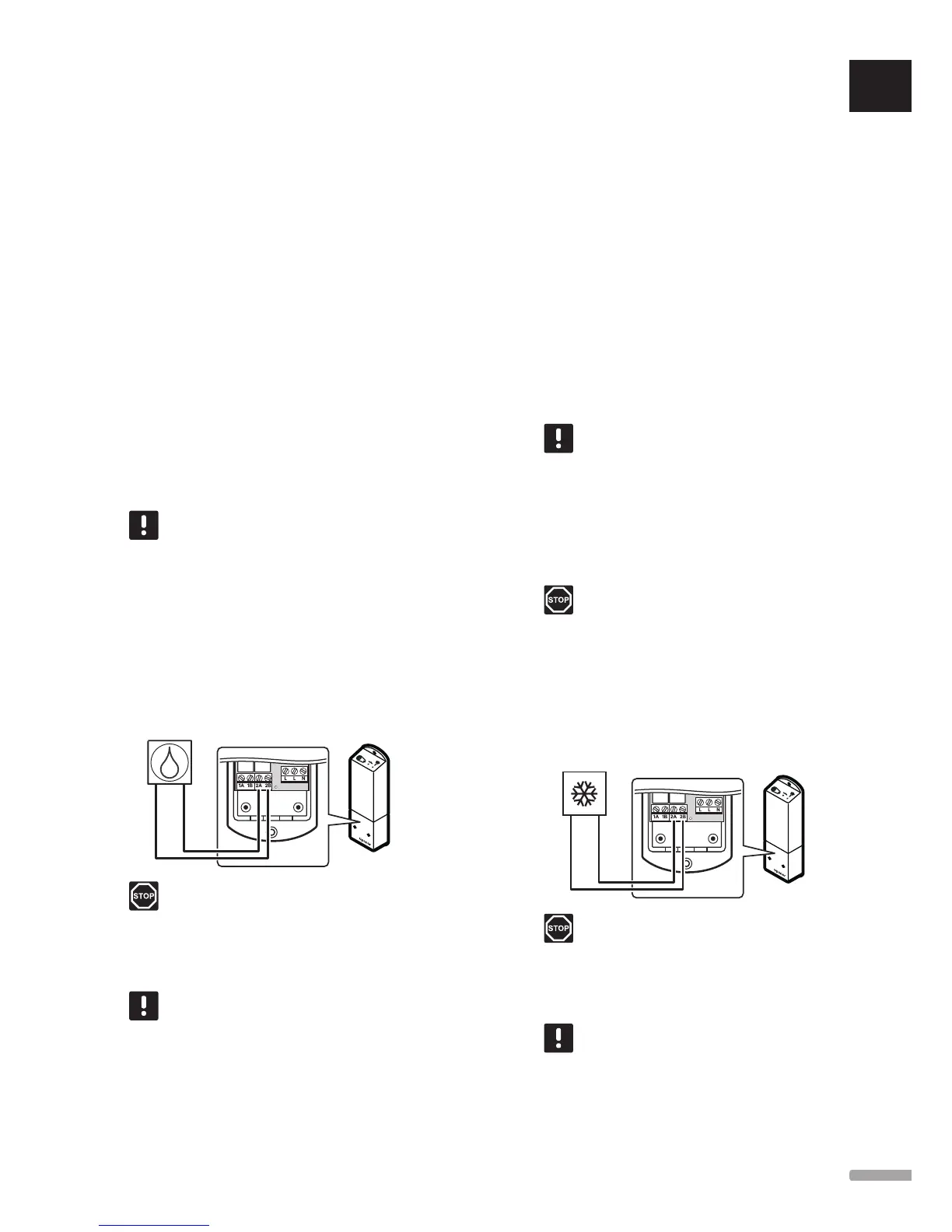
The illustration below shows a dehumidifier connected
to a relay module.
Warning!
Electrical installation and service behind
secured 230 V AC covers must be carried
out under the supervision of a qualified
electrician.
NOTE!
This connection requires a dry contact
sensing input in the dehumidifier.
1. Ensure that the power is disconnected from both
the relay module and the dehumidifier.
2. Connect the cable to/from the dehumidifier to the
connector 2A and 2B on the relay module.
3. Register the relay module to the controller as a
Relay module, system device channel 2. See
section 5.8 Register relay module M-161 for
installation of the relay module.
4. Go to menu Integration in the interface and select
Relay module.
5. Select the controller to which the relay module is
registered and select Pump + Dehumidifier.
A dehumidifier is now connected to a relay module and
activated.
Connect chiller (optional)
The system can control up to four chillers, one per
relay module. The chiller starts when there is a cooling
demand while in cooling mode. It will stop when the
cooling demand is met.
NOTE!
See the chiller supplier documentation and
the relevant Uponor wiring diagram before
performing the connection.
The controller uses an output on the Uponor Smatrix
Relay Module M-161 for this purpose. Only one chiller
can be controlled per controller. This output is a dry
contact relay output.
Warning!
Electrical installation and service behind
secured 230 V AC covers must be carried
out under the supervision of a qualified
electrician.
To connect a chiller to a relay module (Wave PLUS
with interface only):
The illustration below shows a chiller connected to a
relay module.
Warning!
Electrical installation and service behind
secured 230 V AC covers must be carried
out under the supervision of a qualified
electrician.
NOTE!
This connection requires a dry contact
sensing input in the chiller.
1. Ensure that the power is disconnected from both
the relay module and the chiller.
UK
CZ
DE
DK
EE
ES
FI
FR
HR
HU
IT
LT
LV
NL
NO
PL
PT
RO
RU
SE
SK
33
UPONOR SMATRIX WAVE/WAVE PLUS
· INSTALLATION AND OPERATION MANUAL