RoboSHOT HD Cameras
RoboSHOT HD Cameras - Document Number 342-0796 Rev C Page 12 of 68
Quick-Connect USB Interface
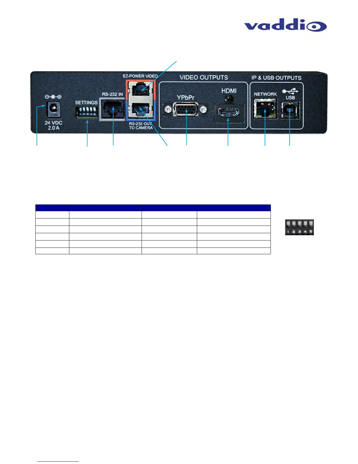
Image: Rear Panel with Feature Call-outs
1) Power Input: 5.5mm OD x 2.5mm ID coaxial connector for the provided 24 VDC, 2.0 Amp switching power supply. The Quick-
Connect USB Supplies Power to the attached camera.
2) 5-Position DIP Switch: A 5-position DIP switch allows the user to choose the HD video color space (YCbCr for HDMI and sRGB
color space for DVI-D) on the HDMI output, configure for updates, and restore factory defaults when cycling power.
Table: Quick Connect USB Rear Panel DIP Switch Settings
3) RS-232 IN (Color Coded Grey): Serial RS-232 input on a RJ-45 connector. This control port allows a Vaddio joystick controller
or 3
rd
party controller (Crestron/AMX) to control the camera functions if the embedded webserver is not used for real time control.
4) RS-232 OUT TO CAMERA (Color Coded Blue): Serial RS-232 output on RJ-45 connects via Cat-5 to the camera RS-232 input
on the camera. Control signals from the embedded webserver are sent via RS-232, or RS-232 from external controllers is relayed
to the camera over this control port.
5) EZ POWER VIDEO Port (Color Coded Orange): RJ-45 jack used to supply 24 VDC power to the camera and return differential
video from the camera on Cat-5 cable at a maximum distance of 100’ (30.48m) with PTZ cameras and up to 150’ (45.7m) with
stationary POV cameras (i.e. ZoomSHOT and WideSHOT).
6) YPbPr Output: Analog component video output on a DE-15 (HD15) connector (resolution is set on the back of the camera). The
YPbPr output resolution will be the same as the HDMI output resolution. SD video resolutions (Y/C and CVBS formats) are not
supported by the Quick-Connect USB Interface; however some progressive frame analog component SD video is supported.
7) HDMI Output: The digital video output on the HDMI connector can either be YCbCr color space (normal HDMI mode) or can be
changed to DVI-D color space (sRGB) for older monitors and devices. The HDMI and YPbPr outputs work simultaneously and are
the same resolution (set at the camera).
8) Ethernet 10/100 Network RJ-45 Jack: The Ethernet jack will have yellow and green lights to indicate connectivity and activity of
the network on that jack. The Ethernet jack will stream video (up to 1080p/30 H.264 and can be set from the internal web pages
much like the HD-USB Camera. The resolutions will available in a three (3) stage quality format (High Quality, Good Quality and
Standard Quality targets) and includes a range of CIF to 1080p/30.
9) USB 2.0 Connector: The USB 2.0 is on a Type-B female jack and connects to a PC running a soft-client video conferencing
system or video capture software that uses UVC (USB Video Class) standard drivers. No other USB 2.0 drivers are required to
plug the QC-USB into a computer and have it work. The UVC drivers will auto negotiate the top resolution that the PC and QC-
USB can accomplish together and auto-implement.
Dip Switch Function Default Activation
1
Future Use Up n/a
2
Future Use Up n/a
3
Color Space HDMI Connector Up = HDMI (YCbCr) Down = DVI (sRGB)
4
Program/ Update UP = No Program DOWN = Ready To Program
5
Future Use Up n/a
All Down
Reset to Defaults All UP ALL DOWN (with power cycle)
①
②
④
③
⑥
⑤
⑦
⑨
⑧
 Loading...