RoboSHOT HD Cameras
RoboSHOT HD Cameras - Document Number 342-0796 Rev C Page 13 of 68
B
ASIC
A
PPLICATION
D
IAGRAMS
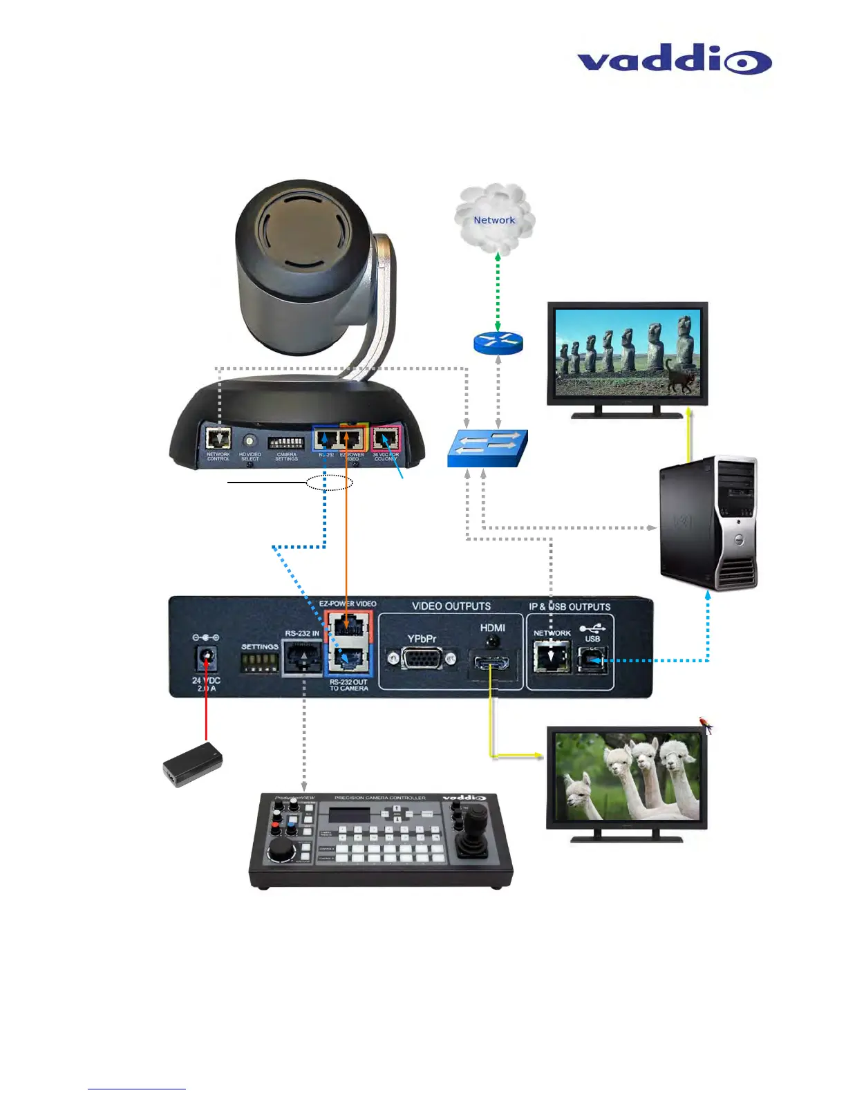
Diagram: Basic Wiring Configuration - UCC Application
RS-232 Cat-5e
(blue to blue)
Quick-Connect
USB Interface
Rear Panel View
24VDC, 2.0 A
Power Supply
(Simulated Video Feed)
ProductionVIEW Precision Camera Controller
Note: RS-232 can be run directly to the camera or
throu
h the
uick-Connect USB as in this confi
uration
RS-232
Control
HDMI
Video
Two Cat-5e Cables
Distance up to 100’ (30.48m)
Self -view Monitor
USB
2.0
(UVC)
HDMI or RBGHV
Far End and PC Monitor
(Simulated Video Feeds)
Network
Switch
Ethernet
Ethernet for Setup
and Control
IP Network
RoboSHOT HD Camera
Rear Panel View
PC with UCC
Application
Ethernet for
Setup and
Control
Not used with
QUSB Systems
EZ-Power Video
(orange to orange)
 Loading...