34 Air/flue pipe installation manual 8000026412_01
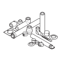
Condition: Replacing the end pipe only
▶ Undo the end pipe's lock (1) using a flat-blade screw-
driver and pull it out to the front.
▶ Slide the deflector onto the terminal piece until you hear
the deflector click into place.
5.14.2.3 Adjusting the deflector
▶ Set the terminal to the required position.
– The flue gas stream is directed upwards at an angle
of approx. 45° when the deflector is set in the centre
position.
– If necessary, the deflector terminal can be rotated 45°
anti-clockwise or clockwise. These setting options
mean that the flue system can be further optimised.
5.14.3 Installing the variable terminal set –
0010039338 /...40 (VTK)
5.14.3.1 Minimum clearances for the flue gas
terminal
If a variable terminal set is connected to horizontal flue pipe-
work, terminal clearances are reduced for the air inlet. The
terminal clearances on the "new" flue outlet at the end of
VTK remain unchanged.
On the VTK, the minimum clearances for the air inlet A, B
and C (→ Installation instructions for the boiler) to openings
(e.g. a window) are reduced to 150 mm. This means that
the terminal will be at the horizontal flue pipework when a
variable terminal set is connected to the air inlet and can
therefore be installed at a clearance of less than 300 mm
from a window opening or a ventilation tile.
5.14.3.2 Scope of delivery
1 Terminal piece (for
0010039338 only)
2 Connection elbow
3 Collar (for 0010039338
only)
4 Terminal elbow
5 Bird-guard grille
6 1 m extension (2 pcs)
7 Pipe clamps (3 pcs)
– Variable terminal set, black, article number 0010039338
– Variable terminal set, white, article number 0010039340
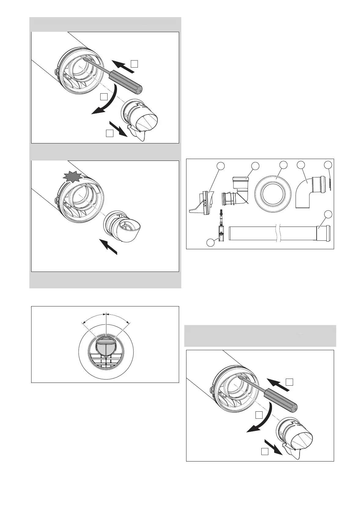
5.14.3.3 Installing the variable terminal set (VTK)
Condition: For 0010039338 only
▶ Replace the terminal piece.
1. Undo the end pipe's lock using a flat-blade screwdriver
and pull it out to the front.