USER'S GUIDE____________________________________________________________________
212 _________________________________________________________________ M210796EN-F
Non-metric units are not available on MODBUS. If they are needed,
calculate the conversion outside the transmitter.
Configuration flags are used to select some basic options of the
instrument and to manually start the sensor operations.
Table 45 Configuration Flag Registers
Name Address Description
Standard filtering on/off 1281 1 = Filtering on
Extended filtering on/off 1282 1 = Extended filtering on
Automatic chemical purge on/off 1283 1 = Automatic purge on.
See configuration register
0773…0774 (1027).
Start-up chemical purge on/off 1284 1 = Start-up purge on
Chemical purge in progress 1285 1 = Purge in progress
(write 1 for manual start)
Sensor heating on/off 1287 1 = Sensor heating on
(optional feature)
Pressure compensation 1288 0 = Measured, 1 = Fixed
Flags 1281 and 1282 are mutually exclusive.
The pressure compensation value is set with configuration registers
0769…0770 (1025) or 0771…0772 (1026).
Some of the configuration registers might not have an effect depending
on the instrument model and configuration.
Other configuration settings are not usually needed and are not available
using the MODBUS interface. The service cable must be used to change
other configuration settings if needed.
Exception Status Outputs
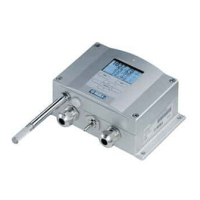
Exception status outputs (read with function code 07) tell the summary of
the PTU300 transmitter status as described in Table 46 below.
Table 46 PTU300 Exception Status Outputs
Output Name Description
0 (0x01) Fault status 1 = No errors
1 (0x02) Online status 1 = Online data available
2 (0x04) Pressure stability 1 = OK
Status information is available also with register access; see section
Status Registers (Read-Only) on page 211.
 Loading...
