USER'S GUIDE____________________________________________________________________
22 __________________________________________________________________ M210796EN-F
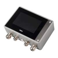
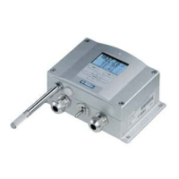
Structure of the Transmitter
1104-078
Figure 1 Transmitter Body
The numbers refer to Figure 1 above:
1 = Signal + powering cable gland, or WLAN antenna connector
2 = Pressure port
3 = Cable gland for optional module
4 = Cover screw (4 pcs)
5 = Display with keypad (optional)
6 = Cover LED
 Loading...
