User’s Guide ______________________________________________________________________
18 ___________________________________________________________________M210925EN-B
0803-029
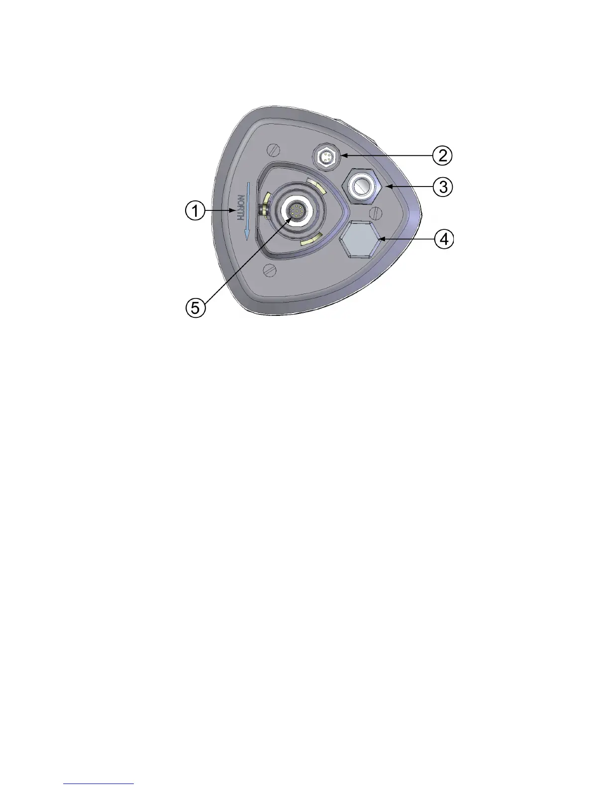
Figure 3 Bottom of the Sensor
The following numbers refer to Figure 3 on page 18:
1 = Alignment direction sign
2 = 4-pin M8 connector for Service Port
3 = Water tight cable gland (optional, included in the Bushing and
Grounding Kit)
4 = Opening for cable gland (if unused, cover with a hexagonal
plug)
5 = 8-pin M12 connector for power/datacom cable (optional)