User’s Guide ______________________________________________________________________
44 ___________________________________________________________________M210925EN-B
Wiring Using the Screw Terminals
1. Loosen the three screws at the bottom of the WMT52.
2. Pull out the bottom part of the sensor.
3. Insert the power supply wires and signal wires through the cable
gland(s) in the bottom of the sensor. Cable glands are included in
the optional Bushing and Grounding Kit (order code 222109).
4. Connect the wires according to Table 2 on page 45.
5. Replace the bottom part and tighten the three screws. Do not
overtighten.
0803-035
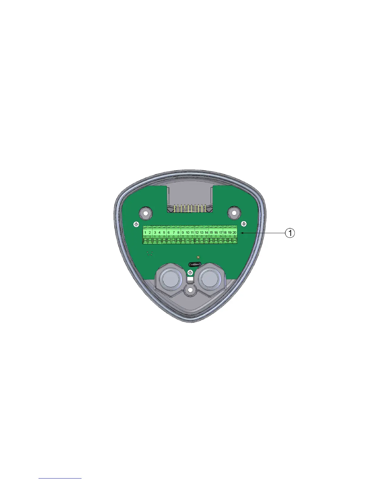
Figure 23 Screw Terminal Block
The following numbers refer to Figure 23 on page 44:
1 = Screw terminals