User’s Guide ______________________________________________________________________
42 ___________________________________________________________________M210925EN-B
Wiring Using the 8-pin M12 Connector
External Wiring
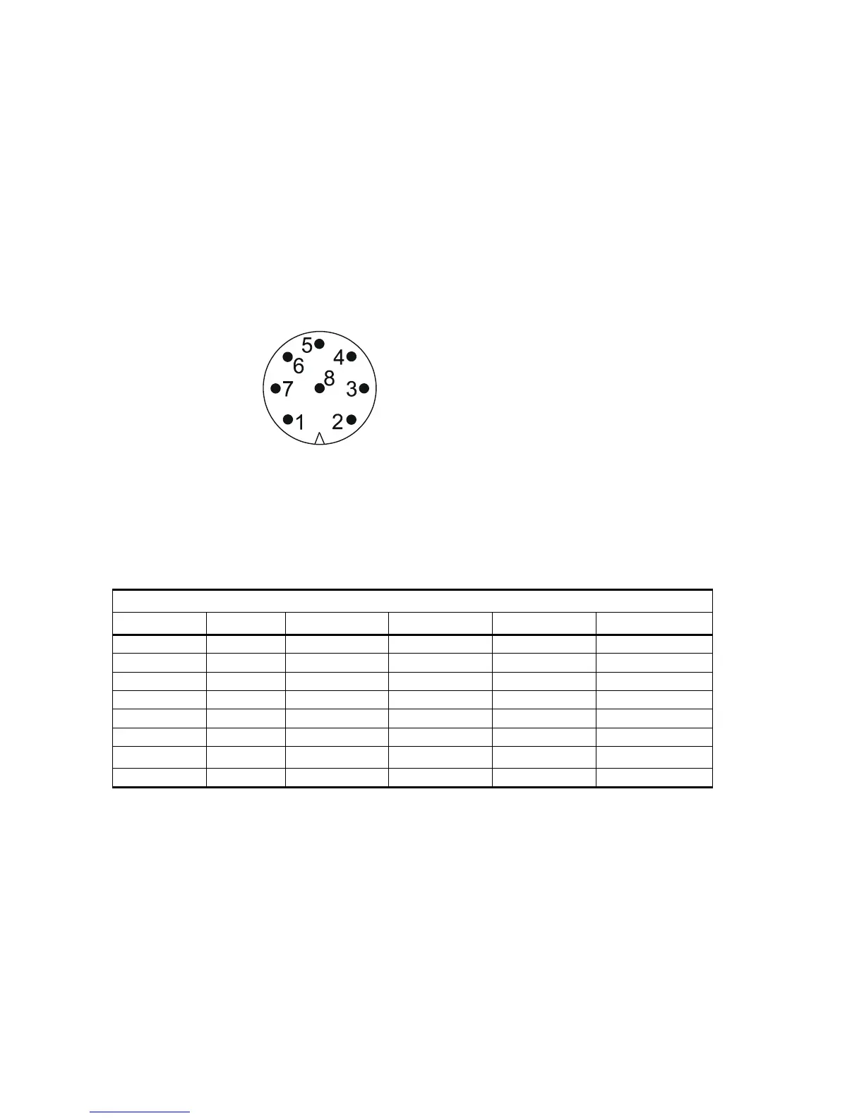
The 8-pin M12 connector (optional) is located on the bottom of the
sensor, see Figure 3 on page 18. The pins of the 8-pin M12 connector as
seen from outside the sensor are illustrated in the following figure.
0308-032
Figure 21 Pins of 8-pin M12 Connector
The pin connections for the 8-pin M12 connector and the wire colors of
the respective M12 cable (optional, 2/10 m) are listed in the table below.
The signal names Data in (RxD) and Data out (TxD) in the table
describe the direction of data flow as seen from the WMT52.
The terms "Default wiring" and "RS-422 wiring" refer to the two
internal wiring options, see the diagrams on the next page.
Table 1 Pin-outs for WMT52 Serial Interfaces and Power
Supplies
/----------------Default wiring----------------\ RS-422 wiring
Wire Color M12 Pin# RS-232 SDI-12 RS-485 RS-422
Blue 7 Data out (TxD) Data in/out (Tx) Data- Data in (RX-)
Gray 5 - - Data+ Data in (RX+)
White 1 Data in (RxD) Data in/out (Rx) - Data out (TX-)
Green 3 GND for data GND for data - Data out (TX+)
Pink 6 GND for Vh+ GND for Vh+ GND for Vh+ GND for Vh+
Yellow 4 Vh+ (heating) Vh+ (heating) Vh+ (heating) Vh+ (heating)
Red/Clear
1
1. Red in the internal wiring, clear in the cable (a non-insulated drain wire)
8 GND for Vin+ GND for Vin+ GND for Vin+ GND for Vin+
Brown 2 Vin+ (operating) Vin+ (operating) Vin+ (operating) Vin+ (operating)