Chapter 5 _______________________________________________ Wiring and Power Management
VAISALA_______________________________________________________________________ 45
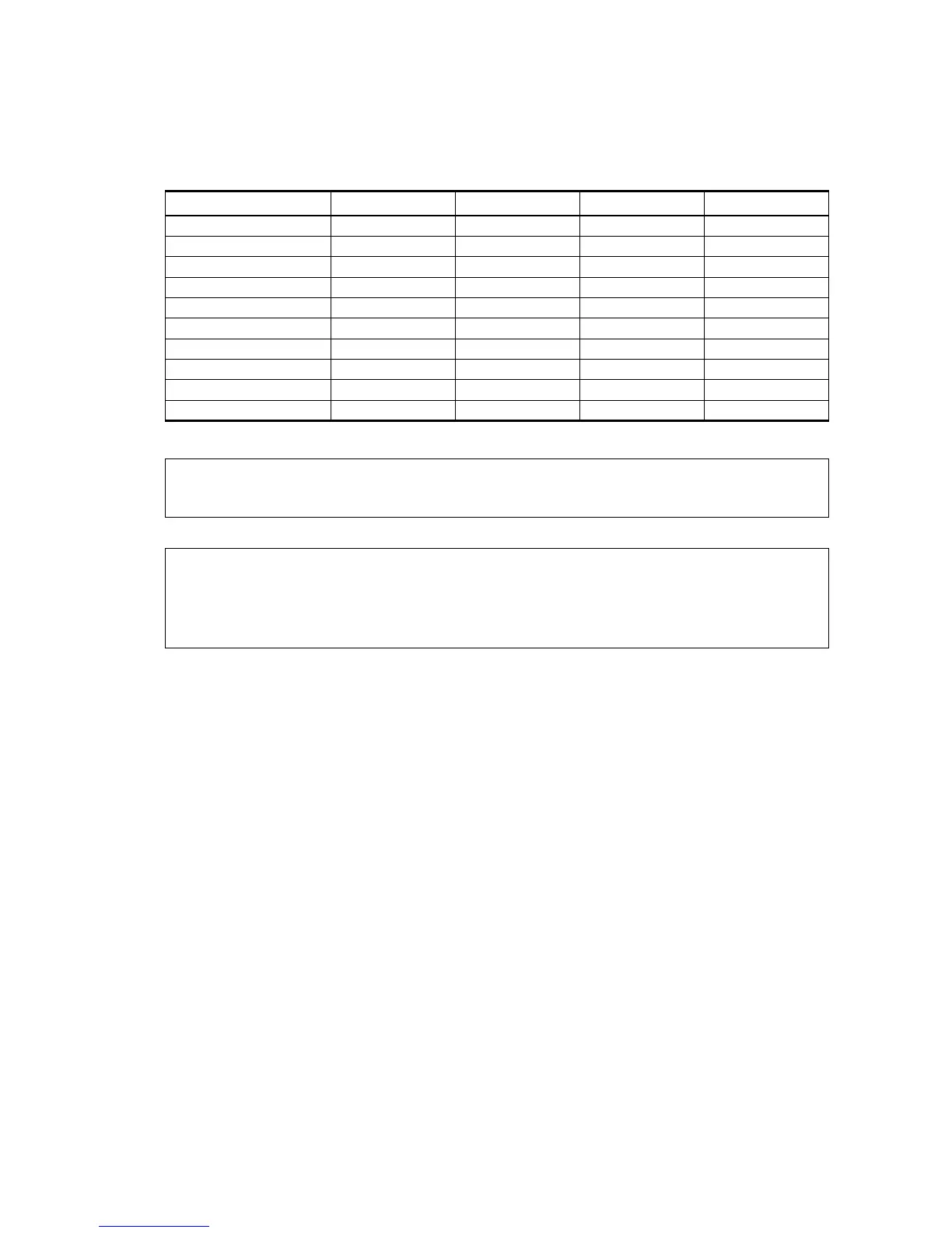
Table 2 Screw Terminal Pin-outs for WMT52 Serial
Interfaces and Power Supplies
Screw Terminal Pin RS-232 SDI-12 RS-485 RS-422
1 RX- - - Data- Data in (RX-)
2 RX+ - - Data+ Data in (RX+)
3 TX- Data out (TxD) Data in/out (Tx) Data- Data out (TX-)
4 TX+ - - Data+ Data out (TX+)
5 RXD Data in (RxD) Data in/out (Rx) - -
6 SGND GND for data GND for data - -
17 HTG- GND for Vh+ GND for Vh+ GND for Vh+ GND for Vh+
18 HTG+ Vh+ (heating) Vh+ (heating) Vh+ (heating) Vh+ (heating)
19 VIN- GND for Vin+ GND for Vin+ GND for Vin+ GND for Vin+
20 VIN+ Vin+ (operating) Vin+ (operating) Vin+ (operating) Vin+ (operating)
NOTE
In the true SDI-12 mode the two Data in/out lines must be combined
either in the screw terminal or outside the WMT52.
NOTE
Short-circuit jumpers are required between pins 1-3 and 2-4 for the
RS-485 communication mode. For the RS-422 mode, the jumpers
need to be removed. In the other modes the jumpers may stay or they
can be removed.