Line Frequency (50-60 Hz) Current Leakage Test Procedure
6-8 Force 2 Service Manual
Important
Line Frequency (50-60 Hz) Current Leakage Test Procedure
This test measures potentially dangerous 50-60 Hz leakage currents.
The Force 2 generator is left on but not active.
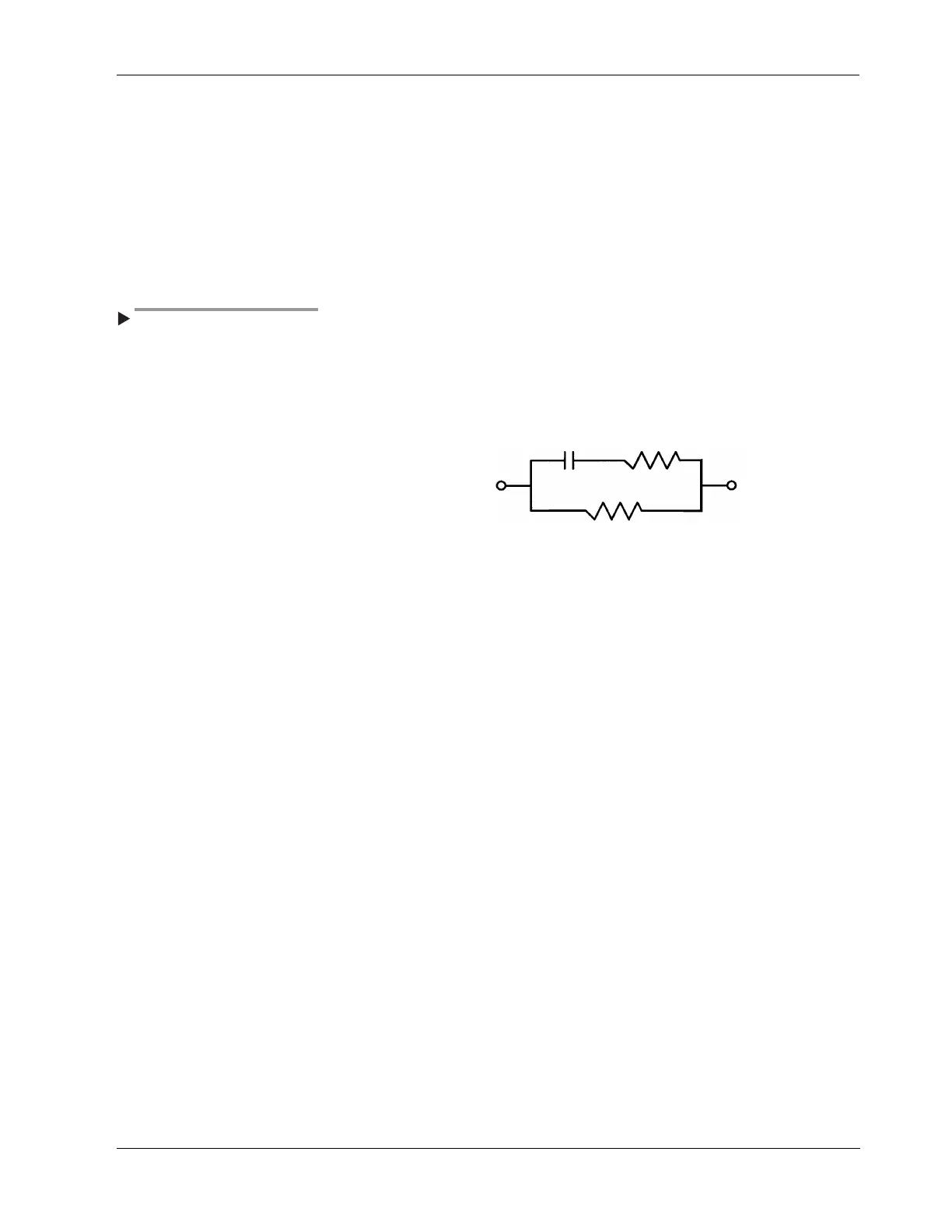
To indirectly measure the current, observe the voltage across a 1k ohm
resistor to ground from each front panel receptacle. A 0.015 µF capacitor
connects in series with the 10k ohm resistor to remove any trace of
oscillator high frequency noise inside the generator. This capacitor has
little effect on the 50-60 Hz leakage current.
When you activate the generator, it
is difficult to make a 50-60 Hz
leakage measurement because of
the extreme difference in
magnitude of the 50-60 Hz leakage
current in the RF signals. When
you activate the generator, there
can be as much as 7000 V peak to
peak of RF compared to 20 mV of
50-60 Hz. This ratio (110 db) of
voltages would require the use of
sophisticated measuring
techniques. In practice, the
50-60 Hz leakage currents do not
change significantly when you
activate the generator.
To calculate the leakage current, use the formula I = E/R, where R = 1k
ohms and E is the voltage across the resistor. The maximum acceptable
voltage across the 1k ohm resistor for 10 µA leakage is 0.010 V (10m V).
Input Circuit:
Measure third wire leakage current by opening the green grounding wire
at the plug and connecting the 1k ohm resistor from chassis to ground.
The maximum voltage across the 1k ohm resistor for 350 µA leakage
would be 350mV. You may use commercially available leakage testers for
this test.
The typical value of 50 µA is valid for manufacturer installed 3 m, 1.0 mm
2 line cords. Do not use longer line cords or extension cords. They
increase the third wire leakage. With the Force 2 generator power off, the
third wire leakage should be less than 10 µA.
The line frequency sink leakage is the current that passes into the PATIENT
leads when there is a 120 V, 50-60 Hz potential between a PATIENT lead and
the chassis. The voltage source should be a 120 V isolation transformer
with a 120k ohm current limiting resistor in series with a secondary.
To calculate the current, measure the voltage across a 1k ohm resistor in
series with the AC volt source and the PATIENT or active receptacles. This
current should be less than 10 µA.
0.015 µF 10k ohms
1000 ohms