viii Force 2 Service Manual
List of Figures
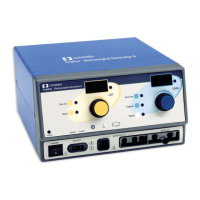
Figure 3-1. PCH Generator Front View 3-2
Figure 3-2. PCH Generator Rear View 3-2
Figure 4-1. PCH Generator Typical Output Power vs Load—Monopolar Cut
Modes 4-6
Figure 4-2. PCH Generator Typical Output Power vs Load—Monopolar Cut
Modes (continued) 4-7
Figure 4-3. PCH Generator Typical Output Power vs Load—Monopolar Coag
Modes 4-8
Figure 4-4. PCH Generator Typical Output Power vs Load—Bipolar Mode 4-9
Figure 6-1. Pure Cut 300 Ω Load
Bipolar 100 Ω Load 6-10
Figure 6-2. Blend 1 300 Ω Load 6-10
Figure 6-3. Blend 2 300 Ω Load 6-11
Figure 6-4. Blend 3 300 Ω Load
Low Voltage Coag 300 Ω Load 6-11
Figure 6-5. Coag 300 Ω Load 6-12
Figure 6-6. 1-Cut/Bipolar
2-Blend 1
3-Blend 2
4-Blend 3/LV Coag
5-Coag 6-13
Figure 6-7. 1-Cut/Bipolar
2-Blend 1
3-Blend 2
4-Blend 3/LV Coag
5-Coag 6-13
Figure 6-8. Open Circuit 120W Coag 6-14
Schematics Supplement
Schematic 1. System interconnect diagram S-4
Schematic 2. Component/connector locations S-5
Schematic 3. Bipolar Display board S-6
Schematic 4. Bipolar Display board S-7
Schematic 5. Heatsink assembly, RF out S-8
Schematic 6. Heatsink assembly, clamp S-9
Schematic 7. Heatsink assembly, power supply S-10
Schematic 8. Heatsink assembly, HVDC S-11
Schematic 9. Monopolar keyboard S-12
Schematic 10. Monopolar keyboard S-12
Schematic 11. Footswitch board S-13