Home
Valleylab
Portable Generator
Force 2-2 PCH
Page 17 (Controls, Indicators, and Receptacles)
Valleylab Force 2-2 PCH - Controls, Indicators, and Receptacles
74 pages
Manual
Save Page as PDF
To Next Page
To Next Page
To Previous Page
To Previous Page
Loading...
SECTION
3
Force 2 Service Manual
3
-
1
3
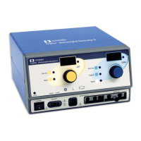
Description of Controls, Indicators,
and Receptacles
This section describes the controls, indicators, and receptacles for
accessories located on the front panel of the Force 2 generator
.
16
18
Table of Contents
Main Page
Conventions Used in this Guide
3
Valleylab Service Centers
4
Table of Contents
5
List of Figures
8
Section 1. Service Warnings and Cautions
11
Section 2. Unpacking and Installation
13
Unpacking the Force 2 Generator
13
Responsibility of the Manufacturer
13
Preparing the Generator for Use
14
Power Requirements
14
Check the Power Connector
14
Ensure Proper Grounding
15
Perform a System Check
15
Section 3. Description of Controls, Indicators, and Receptacles
17
Controls
19
Indicators
20
Alarms
21
Receptacles
21
Rear Panel Functions
22
Section 4. Technical Specifications
23
Standard Conditions of Measurement
23
Operating Parameters
23
Storage and Shipping
23
Output Waveform
24
PCH Generator Output Characteristics
24
Output Configuration
24
Input Power Source
25
Force 2-2 PCH Generator
25
Force 2-8 PCH Generator
25
Line Regulation
25
High Frequency Risk Parameters
26
Low Frequency Leakage (50-60 Hz)
26
Force 2-2 PCH Generator
26
Force 2-8 PCH Generator (Per VDE 0750 (IEC601-1), Section 19 for Class 1 Equipment)
26
REM Contact Quality Monitor
27
Audio Volume
27
Approximate Weight
27
Size
27
Classification
27
Type CF Equipment Per IEC 601-1
27
Drip Proof Per IEC 601-1
27
Output Power Vs. Impedance Graphs
28
Section 5. Circuit Descriptions
33
Bipolar Display
33
Monopolar Control/Display
33
Mode Indicators
34
REM and RMOTE Indicators
35
RF Indicators
35
External Memory
36
Interface
37
Power Supply
38
RF Output
39
Section 6. Maintenance Procedures
41
Routine Maintenance and Inspections
41
Cleaning Instructions
41
General Testing Information
42
Recommended Test Equipment
43
Power up Self-Test
43
Calibration
44
Calibration Procedure
44
REM Test Procedure
47
Line Frequency (50-60 Hz) Current Leakage Test Procedure
48
Bipolar and Monopolar Output RF Leakage Test Procedures
49
Typical Output Waveforms
50
TT-On Waveforms at TP12 on PSRF Board
53
RF Drive Waveforms at TP7-10 on PSRF Board
53
Clamp Waveform at TP11 on PSRF Board
54
Components Replacement Guidelines
55
Section 7. Manufacturer Service
57
Returning the Equipment for Service
57
Returning the Force 2 Generator
58
Returning Circuit Boards and Other Subassemblies
58
Section 8. Service Parts List
59
Ordering Replacement Parts
59
Monopolar Control/Display Board
60
Bipolar Display Board
62
Interface Board
63
Power Supply RF Board
66
Heatsink Assembly
71
RF out
71
Hvdc
71
Clamp
71
Generator Base Assembly
72
Related product manuals
Valleylab Force 2-8 PCH
58 pages
Valleylab SurgiStat II
82 pages
Valleylab Force 2
58 pages
Valleylab Force FX-C
214 pages
Valleylab Force FX-8C
218 pages
Valleylab ForceTriad
100 pages