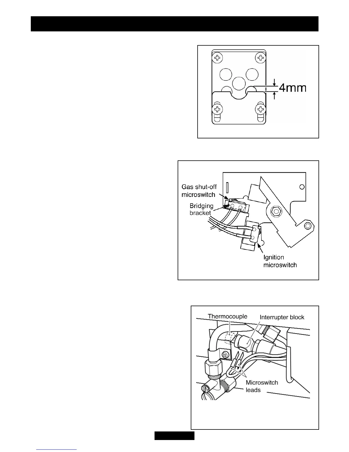
17.1 Checking the aeration setting of the burner.
1. The aeration shutter is factory set and should
not require adjustment. If the shutter is not as
shown in figure 47 and requires adjustment,
loosen the two aeration shutter screws, slide the
aeration shutter to the position shown in figure 47
and tighten the fixing screws.
17.2 To remove the ignition microswitch.
See figures 48 & 49.
The ignition microswitch is stamped V4NT9C4YC
1. Remove the bottom front cover and the fire
front casting.
2. Disconnect the leads from the ignition microswitch (The lower of the two
microswitches - See figure 48).
3. Detach the microswitch and insulation
pad by removing two screws.
4. Replace in the reverse order. Check that
the microswitch operates correctly by fully
closing it and observing that there are
sparks at the pilot electrode.
17.3 To remove the gas shut-off
microswitch.
(See figures 48 & 49).
The gas shut-off microswitch is stamped
V4NT9C2YCGPX or V4NT9C2YCAUX.
1. Remove the bottom front cover and the
fire front.
2. Loosen the thermocouple nut to free the microswitch leads and pull the leads clear
of the thermocouple interrupter block (See
figure 49).
3. Detach the bridging bracket, microswitch
assembly by removing two screws (See figure
48).
4. Replace in the reverse order. When refitting
the leads to the interrupter block, make sure
that they are secured firmly to give a good
electrical contact.
Page 43
© Baxi Heating U.K. Limited 2009.
Figure 49. Thermocouple interrupter
block
INSTALLER GUIDE
Figure 48. Microswitches
Figure 47. Aeration shutter setting