microswitch but before it has pushed the microswitch leaf against the microswitch
body.
When refitting the thermocouple and interrupter block, make sure that the microswitch
wires are properly secured to give a good electrical contact.
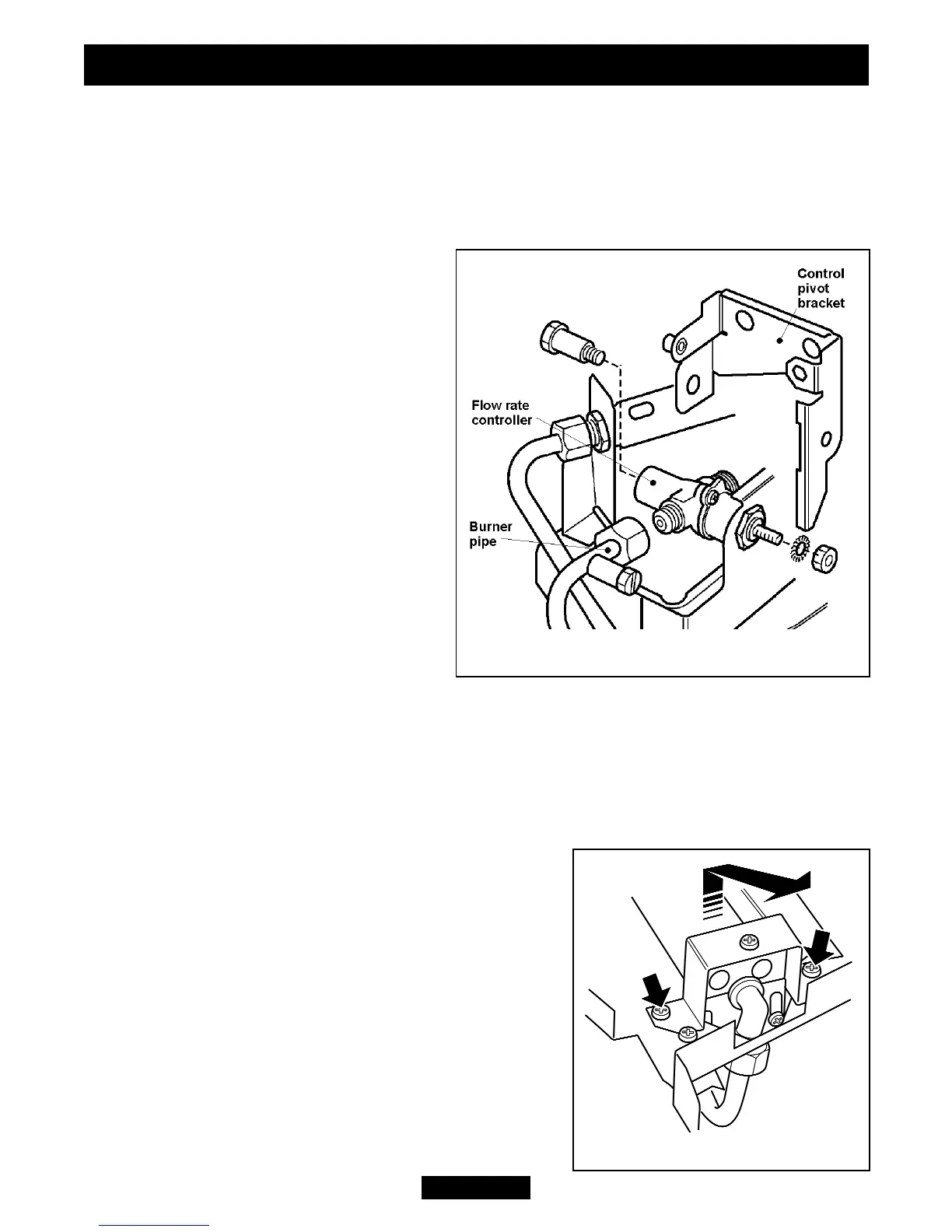
17.12 To remove the gas flow rate controller.
(See figure 59).
1. Remove the burner unit (See section
17.7).
2. If lying the burner on its back, ensure
that the work surface is suitably
protected This will avoid damage to the
work surface.
3. Detach the microswitch cover (See
section 17.2 paragraph 2).
4. Detach the shut-off tap as detailed in
section 17.11 paragraphs 2-6.
5. Detach the burner pipe from the
controller. Support the controller while
detaching to prevent excessive strain.
6. Remove the nut and washer securing
the control pivot bracket to the controller
at the front. Support the pivot bracket
while removing the nut to prevent
possible damage to the microswitch.
7. Remove the hexagonal bolt securing the control pivot bracket to the controller at
the rear.
8. Detach the control pivot bracket.
9. Remove the hexagonal nut securing the controller to the front mounting bracket
and remove the flow rate controller.
10. Refit in the reverse order.
17.13 To replace the burner.
(See figure 60).
1. Remove the burner unit (See section 17.7).
2. Support the elbow injector and unscrew the
injector nut.
3. Remove the two screws from the burner clamping
plate (See figure 60)
4. Lift the right hand side of the burner, slide it to the
right and lift clear
5. Refit in reverse order.
Page 49
© Baxi Heating U.K. Limited 2009.
INSTALLER GUIDE
Figure 60. Removal of burner
Figure 59. Flow rate controller