Connecting Probe/Sensor Wiring to Consoles TLS-350/ProMax/EMC Consoles
68
4-RELAY OUTPUT MODULE - POWER BAY
The 4-Relay Output Module incorporates four Form-C relay outputs and the I/O Combination Module incorporates
two Form-C relay outputs.
Important Output Relay Connection Restrictions
1. Do not connect output relays to a device that draws more than 2 amperes of current. Output power: output
relay contact, resistive load - 120 Vac, 2 A max.; or 24 Vdc, 2 A max.
2. Alarm relays cannot be used for flow control. Alarm relays provide only a momentary closure and cannot
actuate flow control devices such as valves and pump motor relays for extended periods of time.
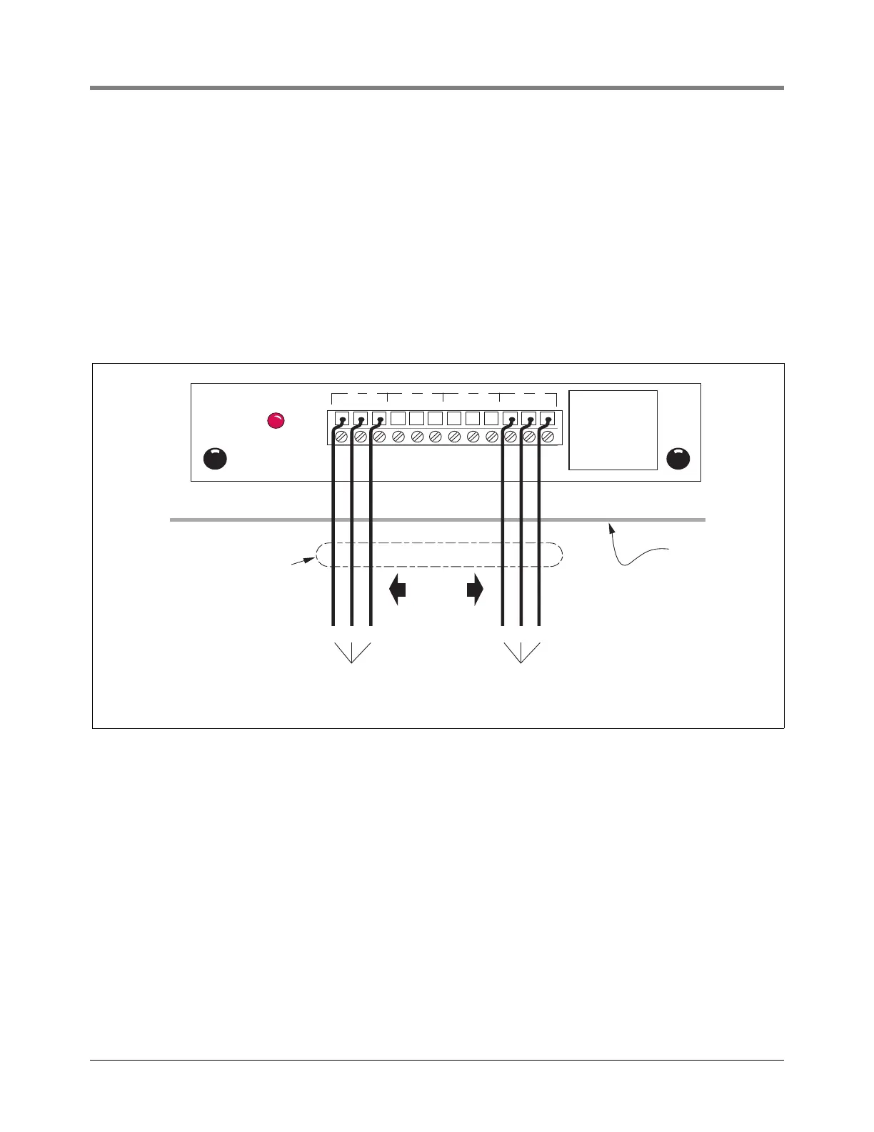
Connect the wires from each external device to the appropriate terminals on the output module [see Figure 66].
Figure 66. 4-Relay Output Module Wiring
RELAY
1 2
4-RELAY OUTPUT MODULE
NC NO C
1
NC NO C
2 3
NC NO C
3
NC NO C
44
Console
NC NO C
External
Device
NC NO C
External
Device
Up to 4
external
devices
consoles\4r0mw.eps
Rigid Conduit (enters
Console through a
Power Bay knockout)
RELAY RATINGS
FORM C CONTACTS
120 VAC 2A MAX
24 VDC 2A MAX
FUSE RATINGS
2A 250VAC TYPE T
(SLO-BLO)
Relay Output
Wiring #14 AWG
 Loading...


