Connecting Probe/Sensor Wiring to Consoles TLS-350/ProMax/EMC Consoles
71
PUMP SENSE MODULE - POWER BAY
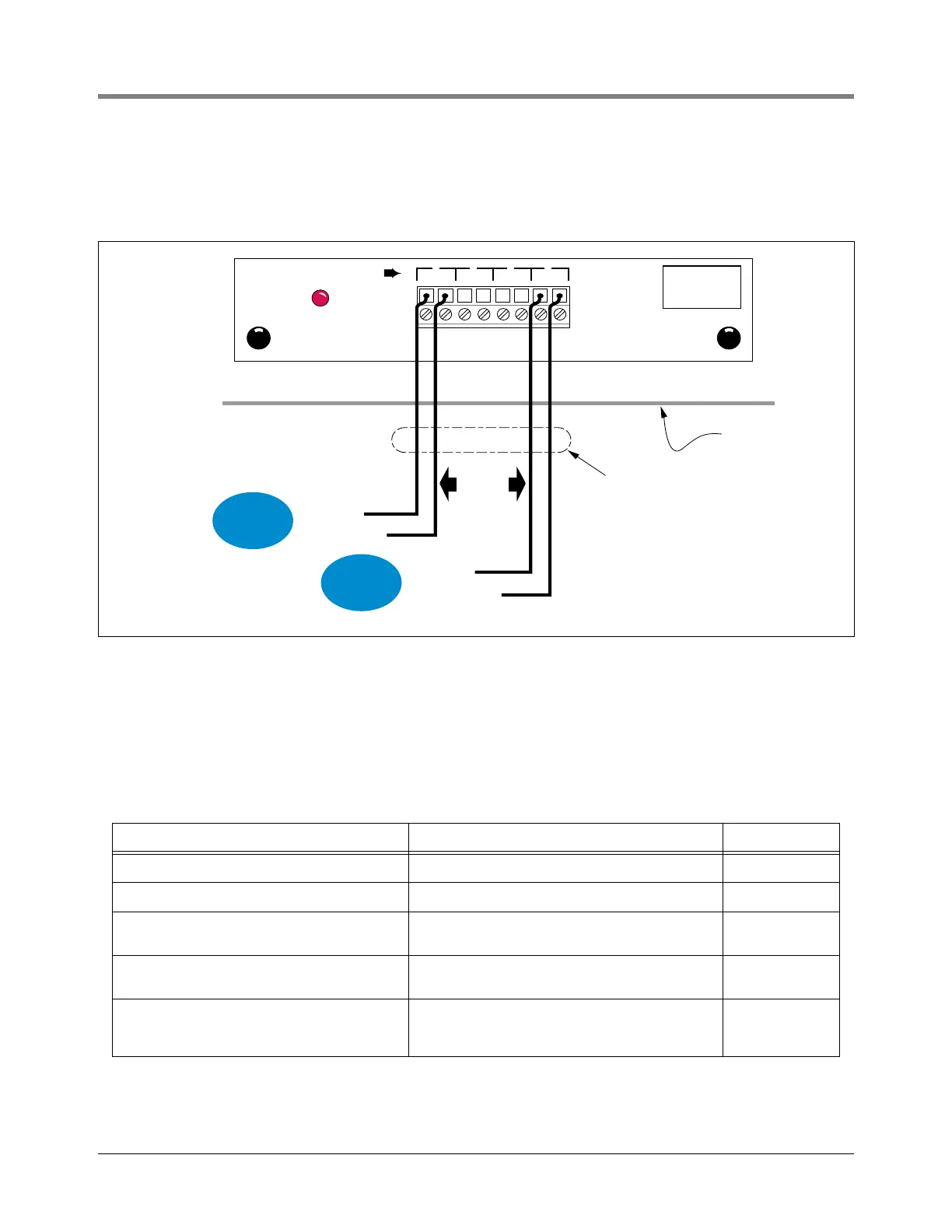
Connect the two color-coded or marked wires from the pump controls to the appropriate terminals on the Pump
Sense Module [see Figure 69].
Figure 69. Pump Sense Module Wiring
WIRING ADDITIONAL POWER BAY MODULES
The wiring diagrams for Power Bay modules not covered in this manual can be found in the separate Veeder-Root
manuals listed below. Follow the instructions in the manual shipped with the module.
Module Description Manual No.
Pressure Line Leak Controller Modules Required with Pressure Line Leak Detection. 576013-499
Line Leak Interface Module Required with Volumetric Line Leak Detection. 576013-765
WPLLD Controller Module
Required with Wireless Pressurized Line Leak
Detection. 577013-481
WPLLD AC Interface Module
Required with Wireless Pressurized Line Leak
Detection. 577013-481
Mechanical Dispenser Interface Module
Consoles w/BIR only - Dispensing system input
from mechanical dispensers. Accepts inputs
from up to 4 pulsers or pulse/totalizers.
576013-893
INPUT RATING
120 VAC
.15 AMP MAX
PUMP SENSE MODULE
PI PR PI PR PI PR PI PR
PUMP
1 2 3 4
consoles\psmw.eps
Console
Up to 4
Pump
Controls
Pump In
Pump Return
Pump In
Pump Return
PUMP
CONTROL
#1
PUMP
CONTROL
#2
PUMP
CONTROL
#1
PUMP
CONTROL
#2
Rigid Conduit (enters
Console through a
Power Bay knockout)
 Loading...


