Connecting Probe/Sensor Wiring to Consoles TLS-350/ProMax/EMC Consoles
70
PUMP RELAY MONITOR MODULE - POWER BAY
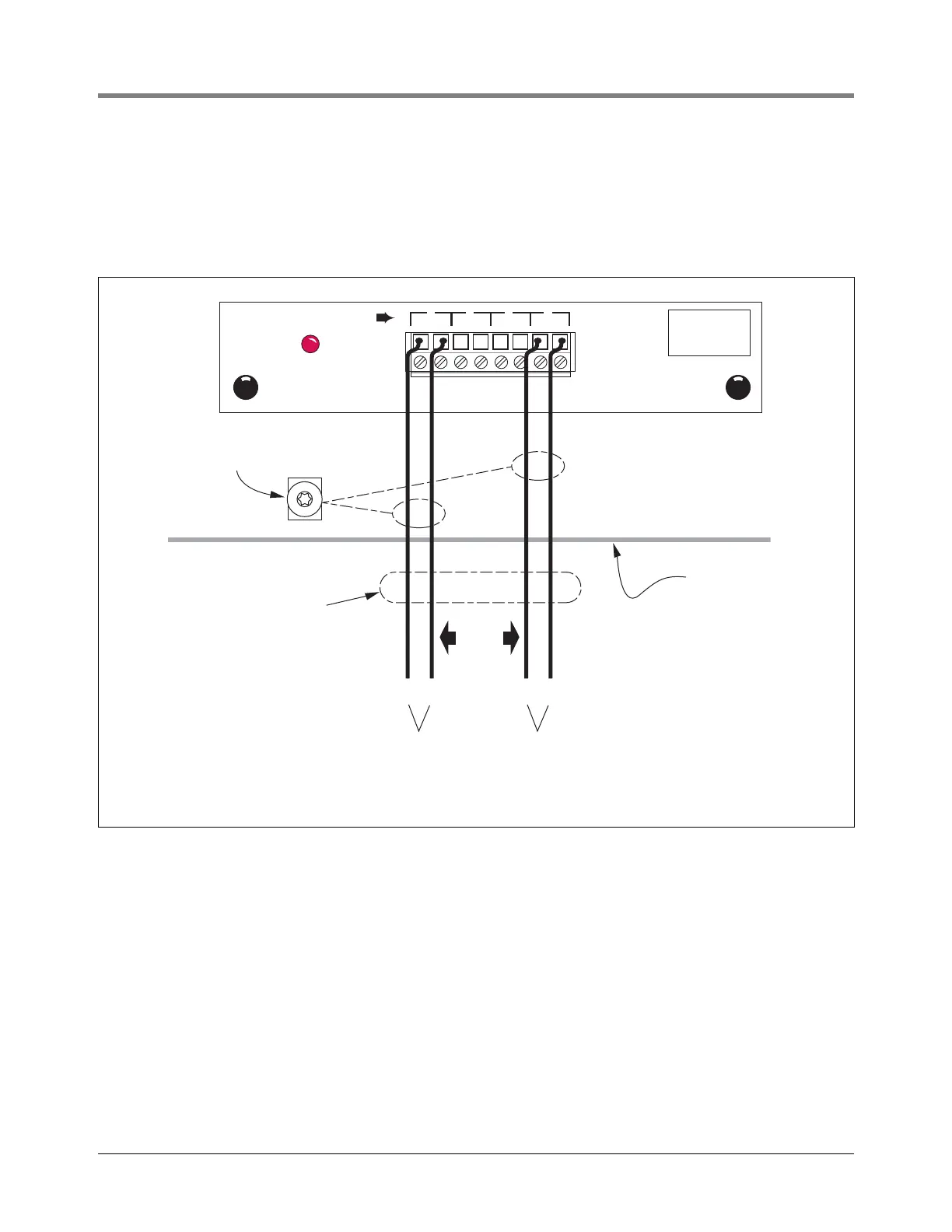
The Pump Relay Monitor Module can accept ac inputs from the STP’s Remote Control Box [Figure 68].]
For each STP to be monitored, connect a shielded cable consisting of two #14 AWG conductors to the
appropriate input terminals on the module.
Figure 68. Pump Relay Monitor Module Wiring
Console
consoles\prmodulerj2.eps
I
N
P
UT
RAT
I
N
G
240
V
AC
0.15
A
M
P
M
A
X
PUMP RELAY MONITOR MODULE
P
I
P
R
P
I
P
R
P
I
P
R
P
I
P
R
P
U
M
P
1 2 3 4
External
ac Input
Wiring
#14 AWG
External
ac Input
Wiring
#14 AWG
Attach Cable Shield to Ground
Lug Closest to Conduit Entry
Shielded
Cables
Rigid Conduit (enters
Console through a
Power Bay knockout)
Up to 4
pumps
M1 M2 M1 M2
 Loading...


