Service And Repair Replacing the Packer-to-Manifold Wiring Connectors
44
21. Remove capacitor access cover (see Figure 37). Remove and discard the O-ring from the cover and set aside
the cover. Observe the three wiring connections from the female connector. Make a note of which wire from
the connector connects to which wire from the incoming power wiring. Cut the incoming power wires from the
female connector wires and discard the connectors.
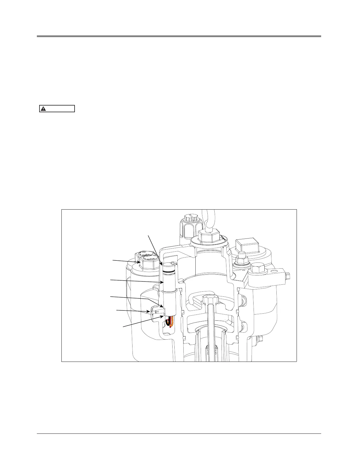
22. Using a 3/16’’ hex wrench, turn the set screw that holds the female connector in place about 1-1/2 turns
counterclockwise until you can lift out the connector (see Figure 37).
Do not try to remove the set screw.
23. Get the new female connector and its 0.862’’ ID x 0.103 wide O-ring from the kit. Push the three wires
coming out of the connector down through the opening in the base of its socket and into the capacitor well.
As you pull on its wires in the capacitor well, lower the connector with the flat cut in the side of the connector
facing its retaining set screw. With the connector as far down as it can go (sitting on the ridge in the base of
its socket), tighten the set screw firmly against the connector. As the set screw tightens it should rotate the
connector to its proper position relative to the male connector.
24. Strip insulation off all six wires 5/16 of an inch (8mm).
25. Reconnect the connector’s three wires as per your notes made in Step 21 above.
26. Get a 2.090’’ ID x 0.118’’ wide O-ring from the Hardware/Seal Kit and lubricate with petroleum jelly. Insert this
O-ring on the capacitor cover and screw in the cover. Do not use thread sealant. Torque the cover to 35 ft-lbs
(50 N•m).
Figure 37. Locating Female Connector Set Screw
27. Remove the manifold’s female connector’s O-ring. Get the 0.862’’ ID x 0.103’’ wide O-ring from the connector
kit and lubricate it with petroleum jelly. Insert this O-ring in its groove in the manifold around the female
connector (see Figure 32 on page 41).
28. Get the three extractable O-ring seals ( 3.975’’ ID x 0.210’’ wide [upper], 3.850’’ ID x 0.210’’ wide [middle],
and 3.725‘’ x 0.210’’ wide [lower]) from the Hardware/Seal Kit. The three O-rings are very close in size so take
3/8'' hex set screw that
holds in female connector
Female connector sits
on ridge in bottom of
socket
Flat cut in side of connector
must face set screw
Male connector in
extractable housing
Female connector in
packer housing
Capacitor
access cover
045-4