25
4 Mounting
VEGAPULS 63 • Modbus and Levelmaster protocol
41364-EN-170711
0 %
100 %
1
2
5
4
3
6
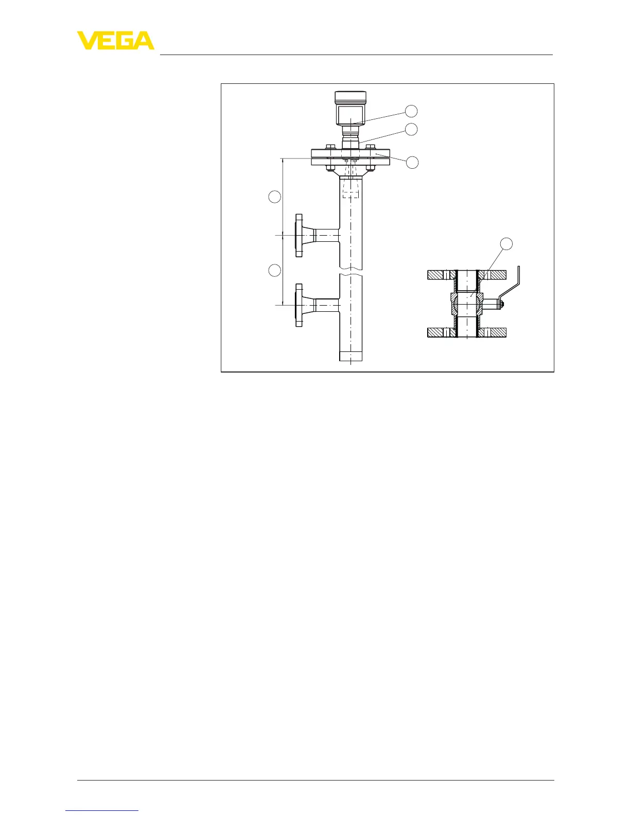
Fig.15:Congurationbypass
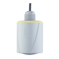
1 Radar sensor
2 Polarisation marking
3 Instrumentange
4 Distance sensor reference plane to upper tube connection
5 Distance of the tube connections
6 Ball valve with complete opening
Instructions of orientation of the polarisation:
•
Note marking of the polarisation on the sensor
•
Withthreadedversions,themarkingisonthehexagon,withange
versionsbetweentwoangeholes
•
The marking must be in one plane with the tube connections to the
vessel
Instructions for the measurement:
•
The 100 % point may not be above the upper tube connection to
the vessel
•
The 0 % point may not be below the lower tube connection to the
vessel
•
Min. distance, sensor reference plane to upper edge of upper tube
connection > 300 mm
•
During parameter adjustment, select "Application standpipe" and
enter the tube diameter to compensate for errors due to running
time shift
•
A false signal suppression with the installed sensor is recom-
mended but not mandatory
•
The measurement through a ball valve with unrestricted channel
is possible
Congurationbypass
Instructions and require-
ments, bypass





 To Next Page