34
6 Set up the sensor with the display and adjustment module
VEGAPULS 63 • Modbus and Levelmaster protocol
41364-EN-170711
6.3 Adjustment system
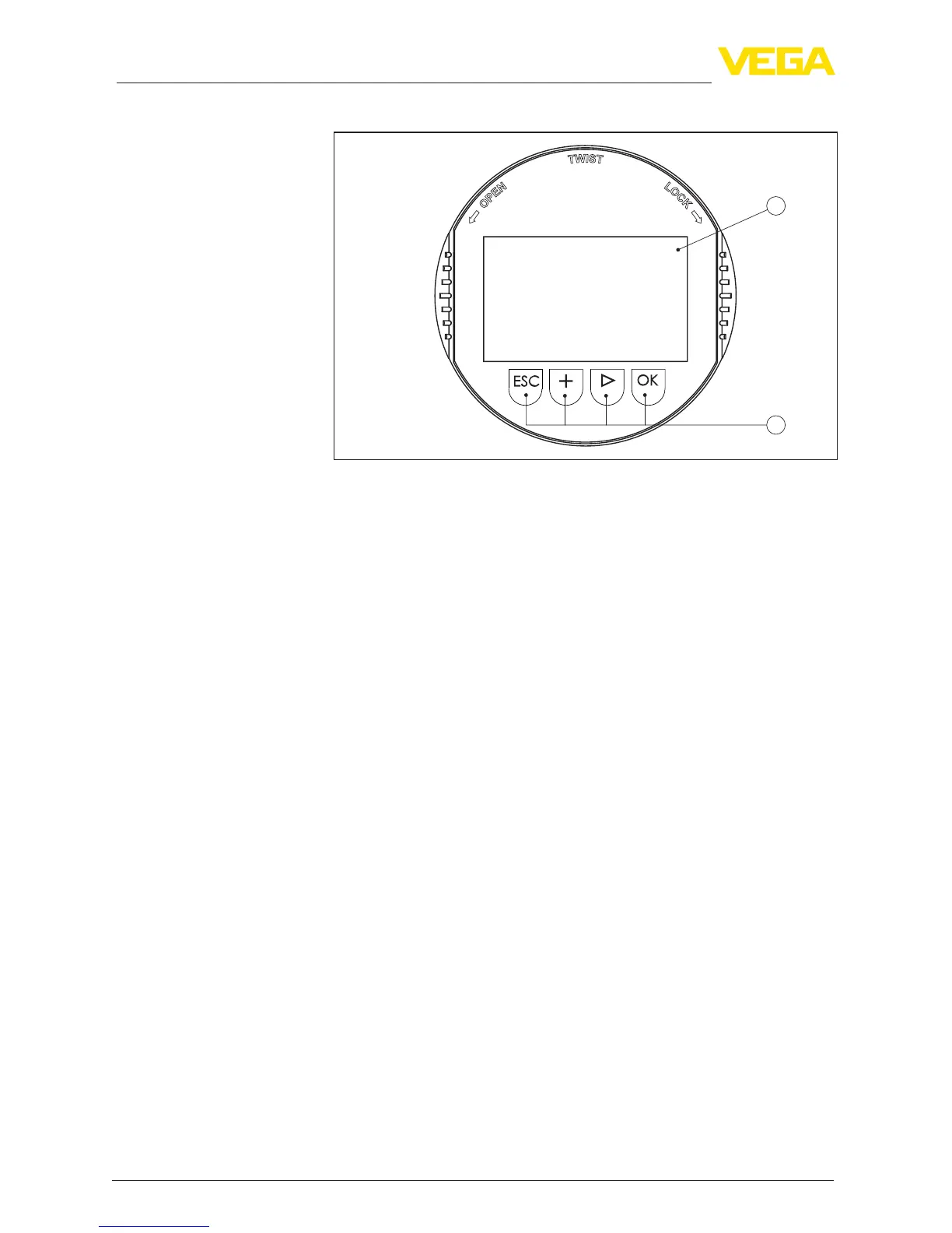
1
2
Fig. 23: Display and adjustment elements
1 LC display
2 Adjustment keys
•
[OK] key:
– Move to the menu overview
– Conrmselectedmenu
– Edit parameter
– Save value
•
[->] key:
– Change measured value presentation
– Select list entry
– Select menu items in the quick setup menu
– Select editing position
•
[+] key:
– Change value of the parameter
•
[ESC] key:
– Interrupt input
– Jump to next higher menu
The instrument is operated via the four keys of the display and
adjustment module. The individual menu items are shown on the LC
display.Youcanndthefunctionoftheindividualkeysintheprevious
illustration.
With the Bluetooth version of the display and adjustment module you
can also adjust the instrument with the magnetic pen. The pen oper-
ates the four keys of the display and adjustment module right through
the closed lid (with inspection window) of the sensor housing.
Key functions
Oper
ating s
ystem - Keys
direct
Adjustment system - keys
via magnetic pen





 To Next Page