79
11 Supplement
VEGAPULS 63 • Modbus and Levelmaster protocol
41364-EN-170711
Pollution degree
6)
4
Protection rating (IEC 61010-1) III
Approvals
Instrumentswithapprovalscanhavedierenttechnicalspecicationsdependingontheversion.
For that reason the associated approval documents of these instruments have to be carefully
noted. They are part of the delivery or can be downloaded under www.vega.com, "Instrument
search (serial number)" as well as in the download area.
11.2 Basics Modbus
Bus description
The Modbus protocol is a communication protocol for the communication between instruments. It is
based on a Master/Slave or Client/Server architecture. By means of Modbus, a Master and several
Slaves can be connected. Each bus participant has an unambiguous address and can send mes-
sages to the bus. This is initiated by the Master, the addressed Slave answers. For data transfer, the
versions serial (EIA-485) as well as the mode RTU are available. In the RTU and ASCII mode inter-
esting here, data will be transmitted in binary form. The telegram consists generally of the address,
the function, the data as well as the transmission check.
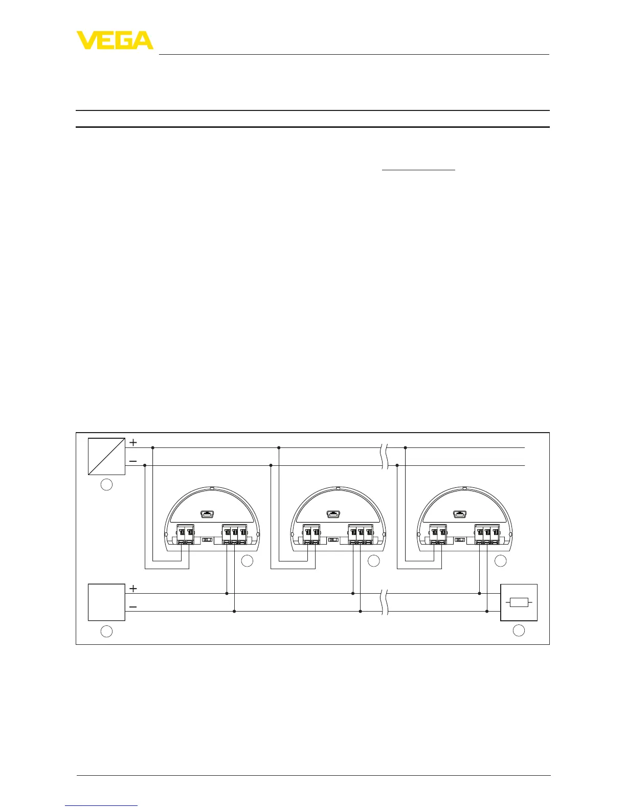
Bus architecture
In the version Modbus RTU, up to 32 participants can be connected to the bus. The length of the
twisted two-wire cable can be up to 1200 m. The bus must be terminated on both sides at the last
bus participant with a terminating resistor of 120 Ohm. The resistor is already integrated in the
VEGAPULS 63 and is activated/deactivated via a slide switch.
4
1
3 3 3
2
+
+
power supply
MODBUS
D0
D1
IS GND
USB
+
+
power supply
MODBUS
D0
D1
IS GND
USB
+
+
power supply
MODBUS
D0
D1
IS GND
USB
1345
2off
on
( )
(
)
(-)
(-)
1345
2off
on
( )
(
)
(-)
(-)
1345
2off
on
( )
(
)
(-)
(-)
Fig. 49: Bus architecture Modbus
1 RTU
2 Connection resistor
3 Bus participant
4 Voltage supply
6)
Whenusedwithfullledhousingprotection

 Loading...


