29
5 Connecting to power supply and bus system
VEGAPULS 63 • Modbus and Levelmaster protocol
41364-EN-170711
Information:
Solidcoresaswellasexiblecoreswithwireendsleevesareinsert-
eddirectlyintotheterminalopenings.Incaseofexiblecoreswithout
end sleeves, press the terminal from above with a small screwdriver,
the terminal opening is then free. When the screwdriver is released,
the terminal closes again.
6. Check the hold of the wires in the terminals by lightly pulling on
them
7. Connect the screen to the internal ground terminal, connect the
outer ground terminal to potential equalisation in case of power
supply via low voltage
8. Connect the lead cable for power supply in the same way accord-
ing to the wiring plan, in addition connect the ground conductor to
the inner ground terminal when powered with mains voltage.
9. Tighten the compression nut of the cable glands. The seal ring
must completely encircle the cables
10. Screw the housing lid back on
Theelectricalconnectionisnished.
Information:
The terminal blocks are pluggable and can be removed from the
housing insert. To do this, lift the terminal block with a small screwdriv-
er and pull it out. When inserting the terminal block again, you should
hear it snap in.
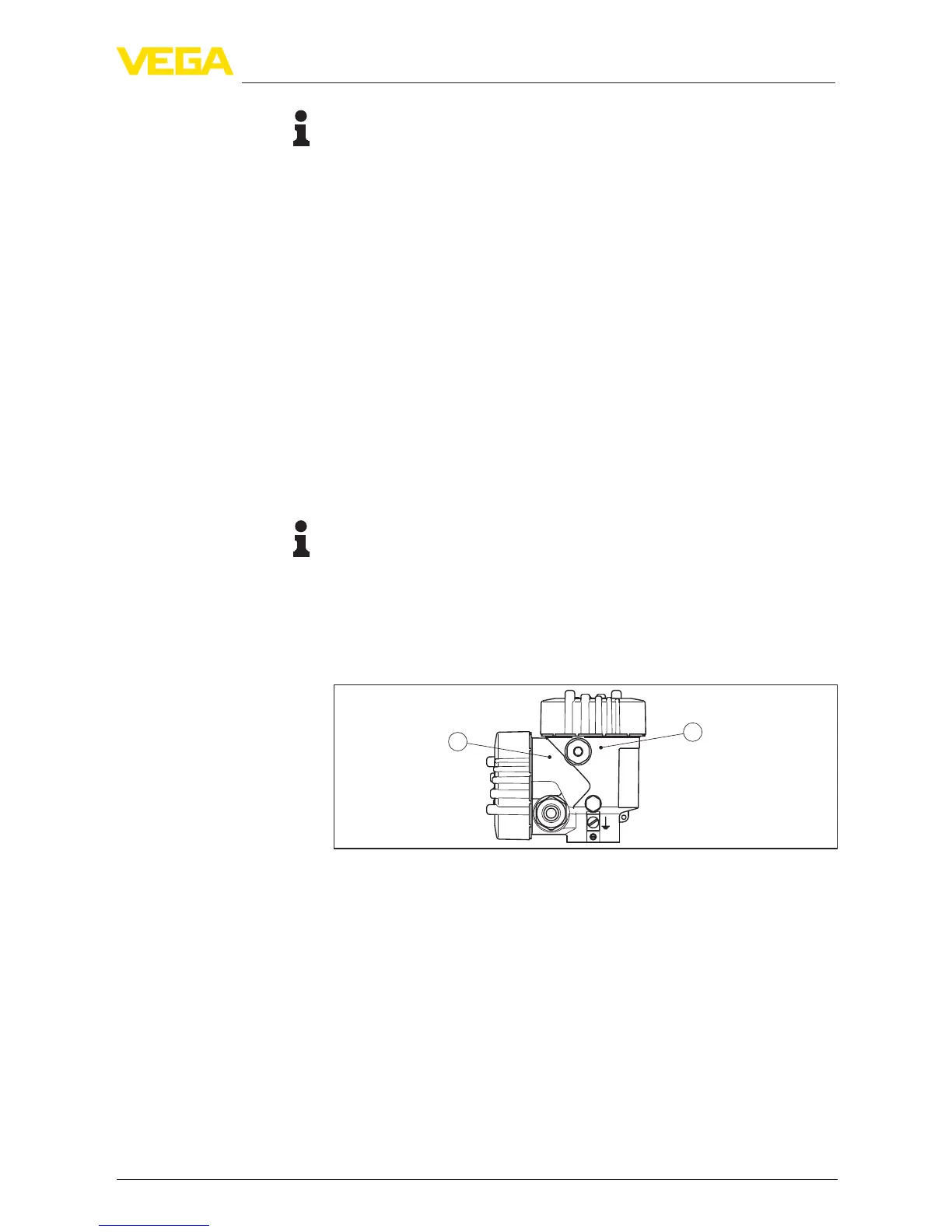
5.3 Wiring plan, double chamber housing
2
1
Fig. 17: Position of connection compartment (Modbus electronics) and electron-
ics compartment (sensor electronics)
1 Terminal compartment
2 Electronics compartment
Overview





 To Next Page