74
11 Supplement
VEGAPULS 69 • Foundation Fieldbus
47251-EN-160815
Electromechanical data - version IP 66/IP 67 and IP 66/IP 68; 0.2 bar
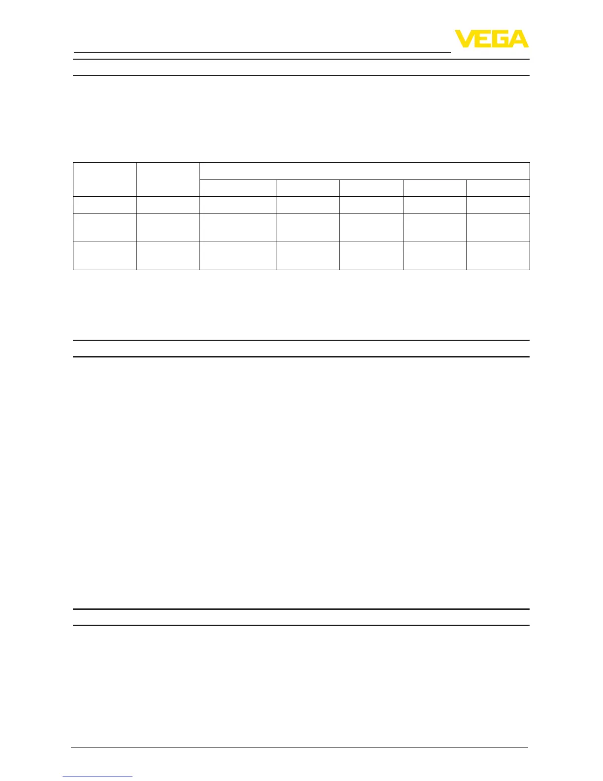
Options of the cable entry
Ʋ Cable entry M20 x 1.5, ½ NPT
Ʋ Cable gland M20 x 1,5; ½ NPT (cable ø see below table)
Ʋ Blind plug M20 x 1.5; ½ NPT
Ʋ Closing cap ½ NPT
Material ca-
ble gland
Material seal
insert
Cable diameter
4.5 … 8.5 mm 5 … 9 mm 6 … 12 mm 7 … 12 mm 10 … 14 mm
PA NBR – ● ● – ●
Brass, nickel-
plated
NBR
● ● ● – –
Stainless
steel
NBR
– ● ● – ●
Wire cross-section (spring-loaded terminals)
Ʋ Massive wire, stranded wire 0.2 … 2.5 mm² (AWG 24 … 14)
Ʋ Stranded wire with end sleeve 0.2 … 1.5 mm² (AWG 24 … 16)
Electromechanical data - version IP 66/IP 68 (1 bar)
Options of the cable entry
Ʋ Cable gland with integrated connec-
tion cable
M20 x 1.5 (cable: ø 5 … 9 mm)
Ʋ Cable entry ½ NPT
Ʋ Blind plug M20 x 1.5; ½ NPT
Connection cable
Ʋ Wire cross-section 0.5 mm² (AWG 20)
Ʋ Wire resistance <0.036Ω/m
Ʋ Tensile strength < 1200 N (270 lbf)
Ʋ Standard length 5 m (16.4 ft)
Ʋ Max. length 180 m (590.6 ft)
Ʋ Min. bending radius 25 mm (0.984 in) with 25 °C (77 °F)
Ʋ Diameter approx. 8 mm (0.315 in)
Ʋ Colour - Non-Ex version Black
Ʋ Colour - Ex-version Blue
Display and adjustment module
Display element Display with backlight
Measured value indication
Ʋ Number of digits 5
Ʋ Sizeofdigits W x H = 7 x 13 mm
Adjustment elements 4 keys