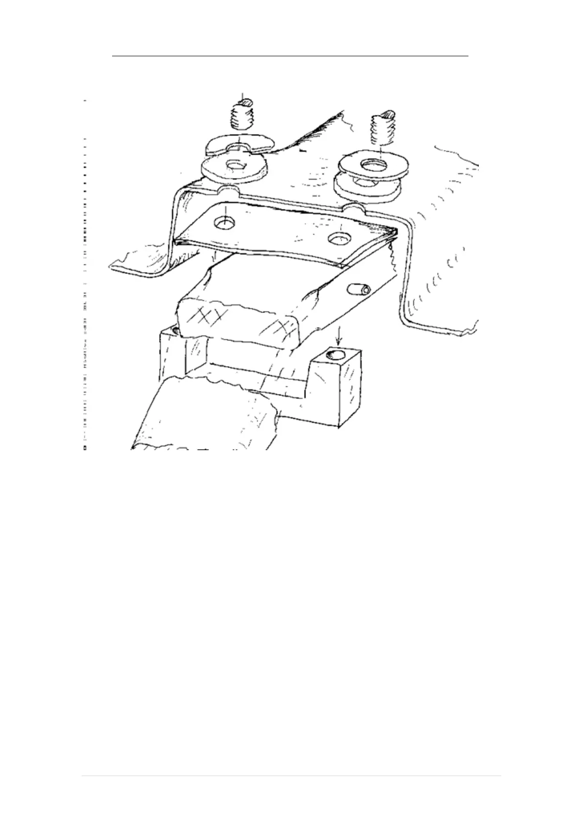
FIGURE - Main gear assembly operation
The mounting bolts will be located 16.5 inches each side of the aircraft’s centerline
(RBL and LBL 16.5), and are 5.5 inches center to center (forward and aft) centered in the
molded recess.. The center gear section should be 5 inches wide at this point., providing
a little more 1-16 inch clearance between the gear and the fastening screws. Using the
heavy bearing washers and the 1/4 inch rubber material provided in the kit on the inside
fuselage side of the mounting holes, the machined U aluminum mounting and screws
provided (9AN6-30A or similar), the trial mount the gear legs to the fuselage (use
minimal torque on the nuts to close gaps but don’t deflect the frame). Make sure the
assembly is square to the centerline of the aircraft, the legs are level on each side, and the
centerline will be located at STA 58. Use thin wood shims nailed in place with 5 minutes
of epoxy to fix any
 Loading...