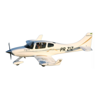
Adjust the spar and ribs into their respective positions. After satisfactory
adjustment, dig the lower edge of them. Make a dry MICRO paste and spread over the
hollow edges. Laminate the inner surface of the spar and the ribs with 2-ply 2-inch-wide
BID tape.
8.4 Aileron control arm preparation
This is a good time to test the aileron fit with the wing assembly. Remove the table
mount and secure the top casing in place with tape. Place the aileron mount in the
respective wing position. The thickness of the aileron must not be so great as to allow
interference with the wing structure with the movement of the aileron. If the aileron is too
thick, disassemble and sand the height of the ribs and spar until the thickness is correct.
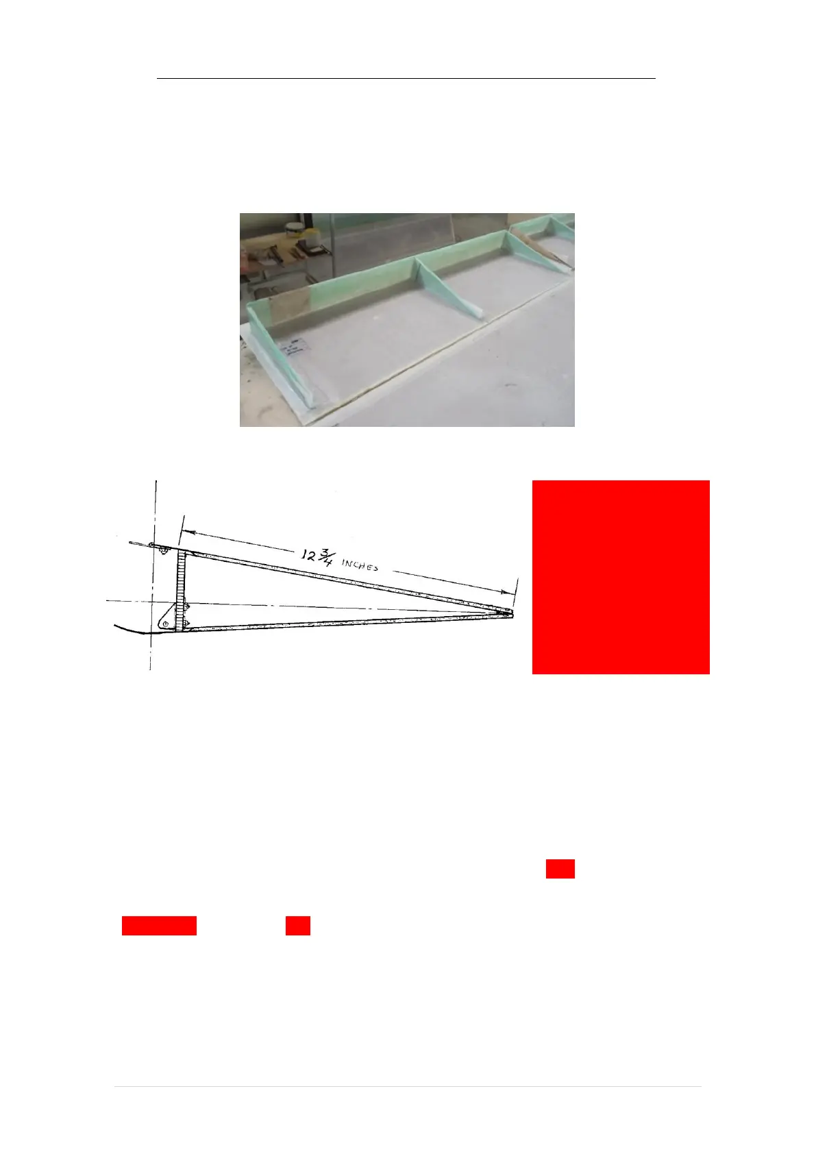
If the hole through the rear wing spar to the aileron actuating arm has not been
drilled to this point, this is a good time to do this. With a cup saw two inches in diameter
or similar tool, drill the holes through the rear spar in line with the actuation arm location
( BL 119.75 center, about 5/8 inches above the inner surface of the lower wing covering.