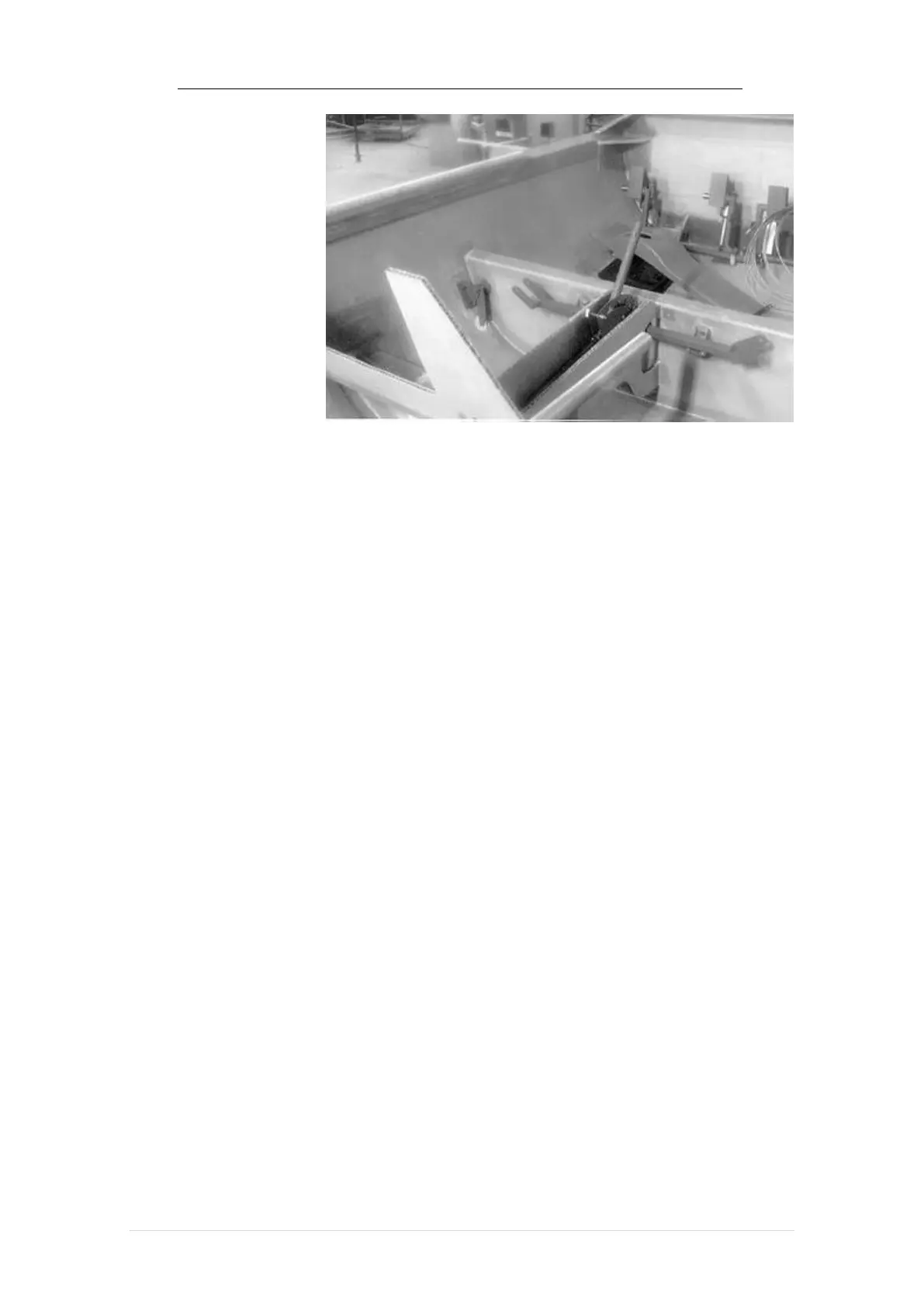
The rudder cables
will be routed within
these sections of the
tunnel at a later stage.
The cables will be
routed inside a plastic
tube, close to each side
of the tunnel walls. Be
aware!
of this requirement in installing and routing other things within the tunnel sections.
6.4 Aileron Horn Installation
The horn aileron, two pieces, left and right, must be fabricated from a 0.125 inch 1
by 1 inch aluminum channel section provided in the kit using the attached drawing.
Fabrication should be easily carried out using simple hand tools such as saws,
spatulas and drills. Locate the pivot point for this link by positioning the face of a KS-3
arm against the rear surface of the front seat gusset, base against the inside wall of the
fuselage with the hole 2 5/8 inches below the top of the front seat gusset (see diagram).