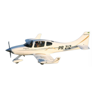
Cut out this spot on both sides. Make 2 lines running through the interior of the
fuselage demarcating the position of the spar. Peel off the liner and core between the lines
in the region near the cutouts. This operation is carried out to make the lower face of the
secondary spar as close as possible to the central casing. Do not remove or trim the outer
casing of the lower fuselage. Note that it is not necessary to remove a central portion of
this cutout. Test the spar fit before doing any trimming so as not to overcut.
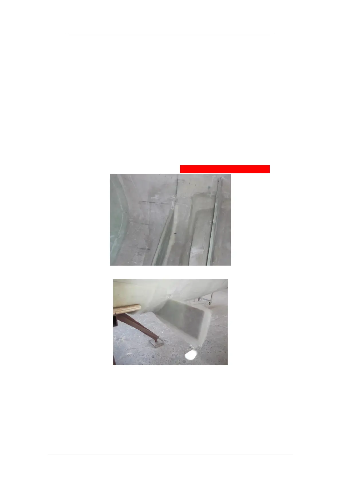
After a satisfactory fit, dig out the core of the exposed parts a little (about 1/8”),
prepare a FLOX paste and pass over the gluing location, center and glue the spar in place.
Use FLOX to make a small radius on both sides of the spar-fuselage junction and laminate
in place with 4 4 inch wide BID tapes (2 inch overlap on each surface).
Laminate the outside with 4 layers of BID 10 inches long by 4 inches wide on each
face of the outer spar on the right and left side.
5.14 Control Console
Many of the control functions are mounted and/or routed through the central
“console”. The console is shaped like a tunnel that runs from the front edge of the