outside, so that the cave of station 185 must be removed and adjusted after these steps.
apply 4 layers of BID inside the fuselage and stabilizer junction with a minimum of
2 inches overlap on both surfaces (inside of the tail cone). The two inner bottom sides
must be glued together, as well as the right inner top side. On outer surfaces scale the
width of the overlap on the outer surfaces (those areas that will be visible and subject to
aerodynamic drag in the finished plane) by applying BID tapes in 2 layers of 4 inches
width, 2 layers of 5 inches wide and more 2 layers of 6 inches wide (6 layers total) to
improve smoothing in these areas for the final aircraft finish.
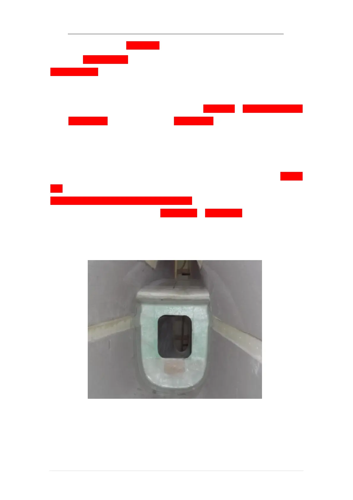
5.12.3 Station 185 Cave Collage
Reposition the cave at station 185 clearing all residues from other operations.
Readjust it in place and sand if necessary, align it vertically. glue in place with 4-layer
BID on the front face covering the inserted rigid points (as mentioned in item 5.8 ) and
overlapping the fuselage by a 2 inch minimum around the edge. On the rest of the
perimeter of the cave, apply a tape of 2 inch wide in 2-layer BID on both sides (work
through hole in frame and rear of fuselage to place BID layers on back.