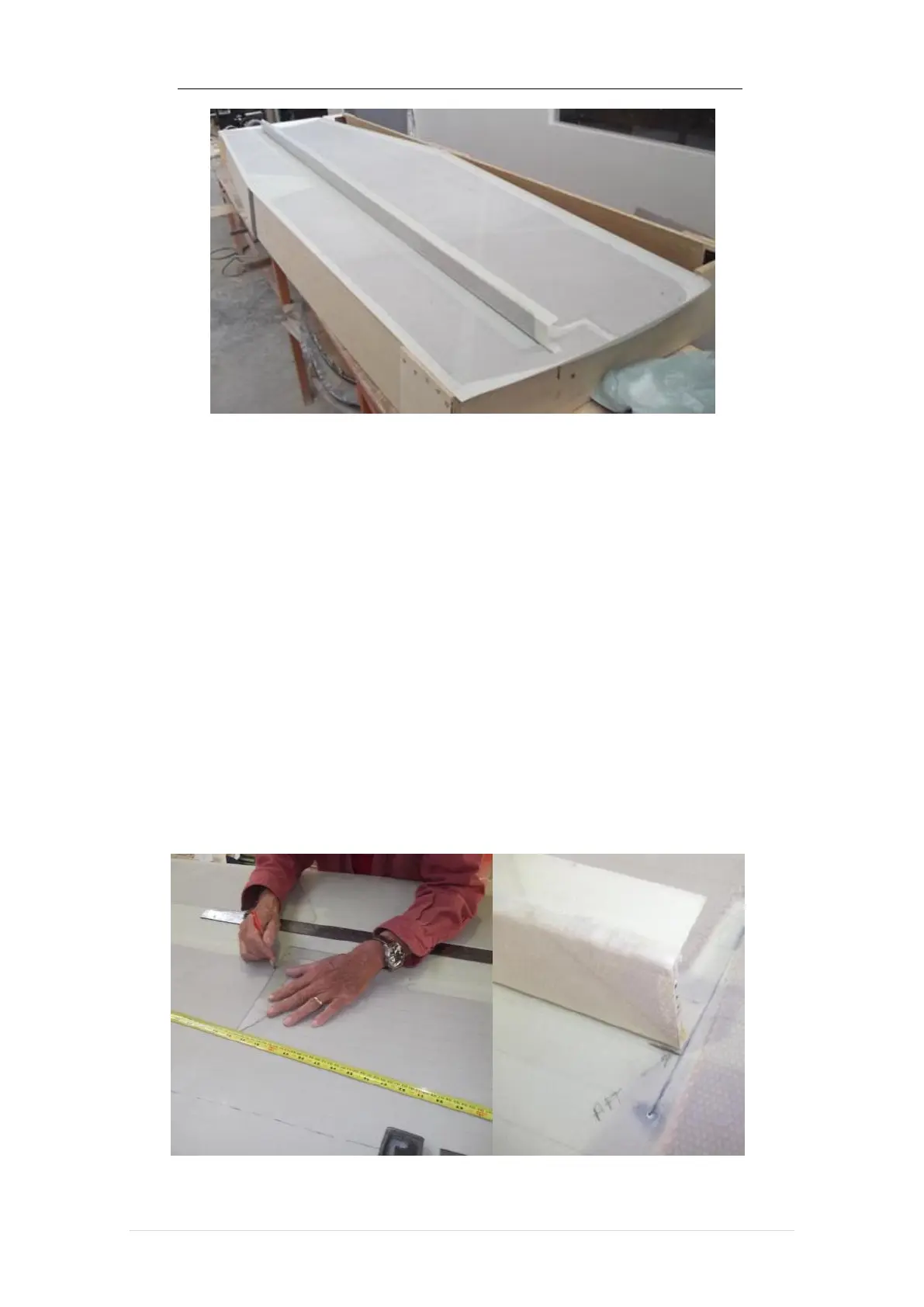
Measure 1 ½ inches in front of the elevator cut line and draw a cut line parallel to
the cut line for positioning the back face of the spar. Similarly draw a straight line 1 ½
inches behind the cut line for positioning the front face of the elevator spar.
Measure and mark the centerline, cut line (Butt-line, BL). 5 left and right and BL-
30 left and right on the top and bottom parts of the cladding. Mark the points where the
left and right BL-57 intersect the horizontal stabilizer spar placement line. Likewise mark
where the left and right BL-59 intersect the leading edge of the horizontal stabilizer. Draw
a straight line between these points (lines for positioning the left and right BL-57 ribs),
and also draw a line parallel to this one passing through the point where the left and right
BL-57 intersect the line for positioning the elevator spar (in this line will be positioned
the closing rib of the elevator horn after cutting the elevator).