8
0900‑5017‑ETEE REV‑05
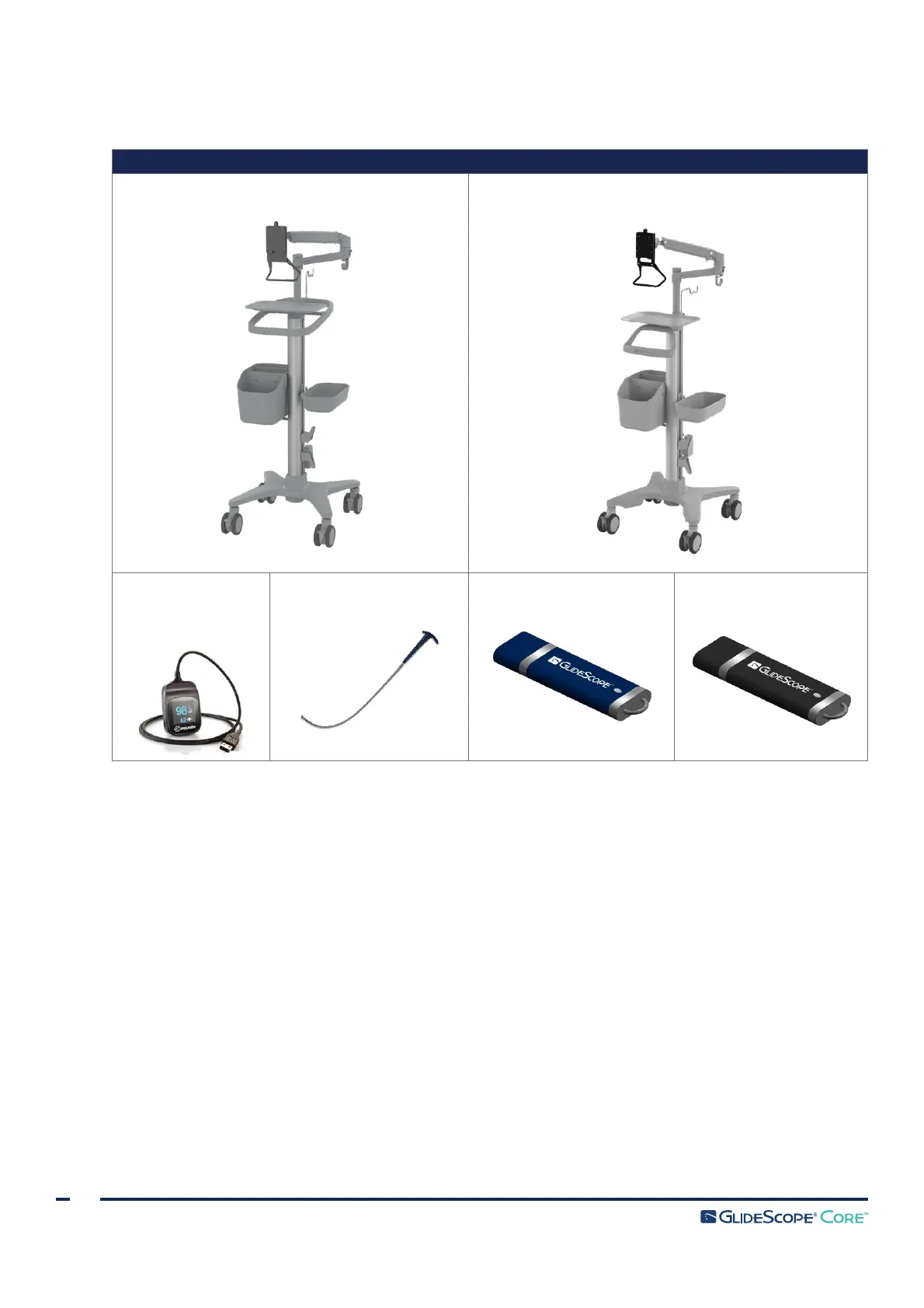
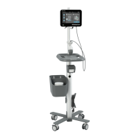
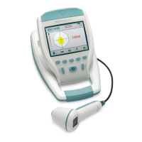
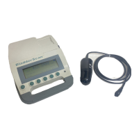
Table 2. Optional System Components
*
OPTIONAL PARTS & ACCESSORIES
Premium workstation (0800‑0557)
Premium workstation (0800‑0636)
Nonin
3231 USB
External Pulse
Oximeter
*
GlideRite Stylets
†
Media storage USB
Operations &
Maintenance Manual USB
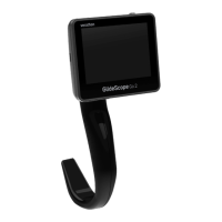
BUTTONS, ICONS, & CONNECTIONS
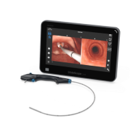
The digital, full‑color GlideScope Core Video Monitor clearly displays the images transmitted from the camera
in the scope. The front of the monitor includes the button for power and the touchscreen.
The back panel of the monitor includes sockets and ports for connecting the power cord, video cables,
USB flash drives, and an HDMI cable for an external video display. When the USB and HDMI ports are
not in use, it is recommended that the rubber cover be used to protect the openings from dust and other
contamination. The back of the monitor also features VESA mounting holes that allow you to attach the
monitor to a GlideScope Core workstation.
The following tables provide general information regarding the buttons and icons on the monitor.
* Not available in all markets.
† For a full list of compatible stylets, please see the GlideRite DLT Stylet Operations & Maintenance Manual (part number 0900‑4841) and
the GlideRite Rigid Stylet Operations & Maintenance Manual (part number 0900‑4686).