REV : 2
REV DATE : 1/17
DPN003451
Page :1 /1
DA080U & DA085U
Form No.: DPN001040_REV4
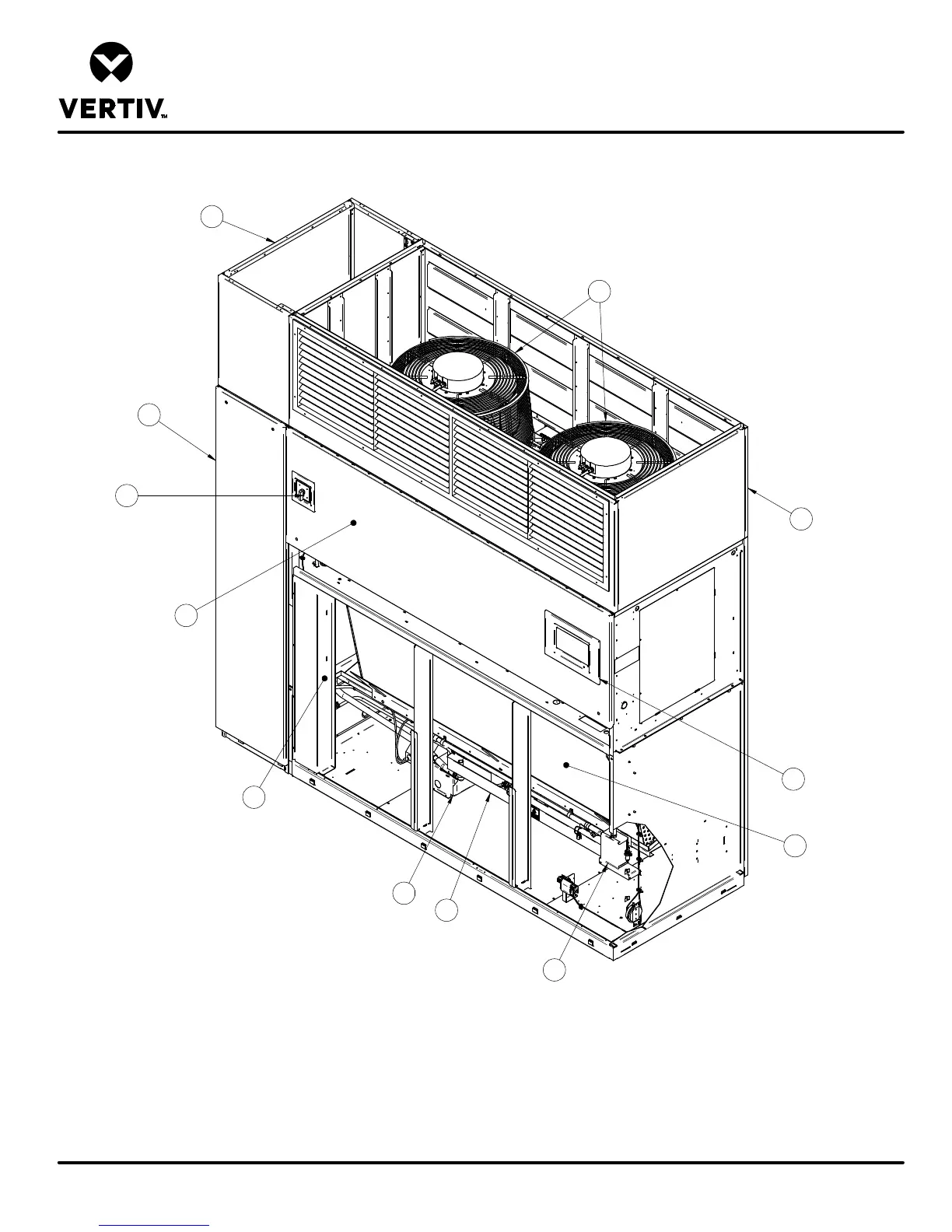
COMPONENT LOCATION DIAGRAM
LIEBERT DSE
1
2
4
5
6
7
8
9
10
11
3 Typ.
1. iCOM Control Display
2. Electric Box
3. Filters (not shown for clarity)
4. Evaporator Coil
5. Compressor Section
6. Infrared Humidifier (optional)
7. Disconnect
8. Condensate Pump (optional)
9. Smoke Sensor (optional)
10. EC Fans
11. Plenum (Front Discharge shown)
12. Compressor Section Plenum (optional, ordered separately)
12