REV : 1
REV DATE : 5/18
DPN004037
Page :1 /1
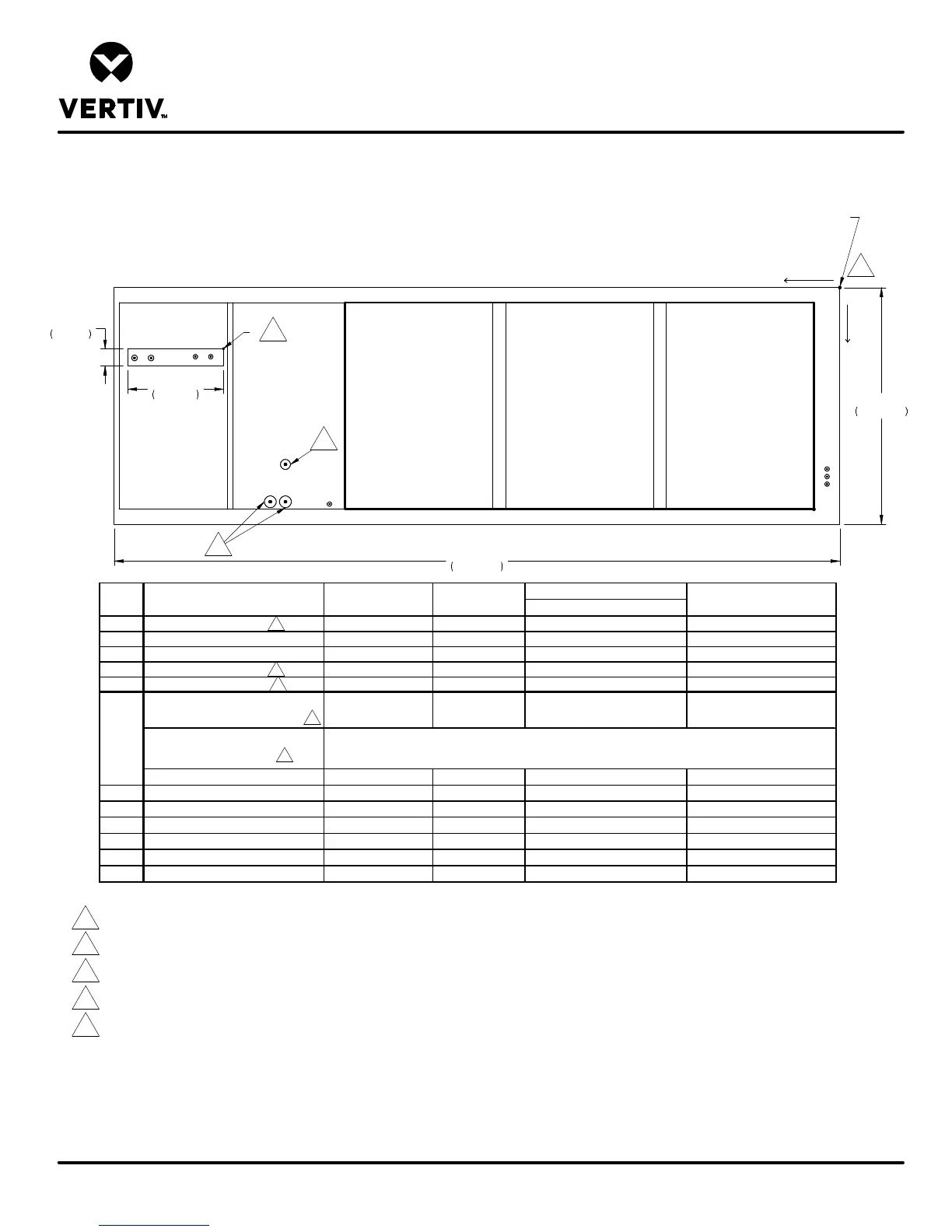
DOWNFLOW AIR COOLED DA150 & DA165 MODELS
WITH AND WITHOUT ECONOPHASE
Form No.: DPN001040_REV4
PRIMARY CONNECTION LOCATIONS
LIEBERT DSE
FRONT EDGE OF UNIT
E1
E2
CD
LV1
LV2
LV3
O
X
Y
ALL DIMENSIONS FROM
REAR CORNER OF UNIT
INCLUDING PANELS
HUM
G1
G2
L1
L2
19"
483mm
3 3/8"
86mm
144"
3657mm
47"
1193mm
R
DX ONLY
CONNECTION SIZE / OPENING
19" (483mm) x 3-3/8" (86mm)
19" (483mm) X 3-3/8" (86mm)
CONDENSATE DRAIN
(infrared humidifier or no humidifier)
110" (2794mm) 35-1/16" (891mm) 1-1/8" FPT 1-1/8" FPT
CONDENSATE DRAIN
(steam generating humidifier)
W/ OPTIONAL PUMP 110" (2794mm) 35-1/16" (891mm) 1/2" O.D. Cu 1/2" O.D. Cu
HUM HUMIDIFIER SUPPLY LINE 101-1/4" (2572mm) 43" (1091mm) 1/4" O.D. Cu 1/4" O.D. Cu
E1 ELECTRICAL CONN. (HIGH VOLT) 113" (2870mm) 42-1/2" (1080mm) 2-1/2" 2-1/2"
E2 ELECTRICAL CONN. (HIGH VOLT) 110" (2794mm) 42-1/2" (1080mm) 2-1/2" 2-1/2"
LV1 ELECTRICAL CONN. (LOW VOLT) 2-1/2" (64mm) 36" (914mm) 7/8" 7/8"
LV2 ELECTRICAL CONN. (LOW VOLT) 2-1/2" (64mm) 37-1/2" (952mm) 7/8" 7/8"
LV3 ELECTRICAL CONN. (LOW VOLT) 2-1/2" (64mm) 39" (991mm) 7/8" 7/8"
YXDESCRIPTIONPOINT
CONSULT FACTORY
DX W/ ECONOPHASE
CD
Notes:
1. Drawing not to scale. All dimensions from rear corner of unit including panels, and have a tolerance of± 1/2" (13mm).
2. Field pitch Condensate Drain line a minimum of 1/8" (3.2 mm) per foot (305 mm). All units contain a factory installed condensate trap. Do not trap
external to the unit. Drain line may contain boiling water. Select appropriate drain system materials. The drain line must comply with all local codes.
3. When piping out the top of the unit, install traps in the discharge lines in the bottom of the unit before running lines to the top.
4. Opening for conduit chase, E1 and E2 are openings for conduit for connections to 2-1/2", 1-3/4" and 1-3/8" knockouts at electric panel.
5. See DPN003175 for alternate piping from the top of the unit.
2
2
4
Blower
Outlet
Blower
Outlet
Blower
Outlet
2
1
5
5
3
3